120hz Lag Testing... Test

Druneau

[H]ard|Gawd
Joined
Jan 3, 2006
Messages
1,745
I've been wanting to test this out for a while and had some free time this morning. I guess what I'd be looking for from this thread is if we can agree/disagree on the testing method and fix it so we can all agree it's giving us consistent/useful results.

What I've done is:
-Use RefreshRateMultiTool
-Windows XP (tried getting my CRT above 85hz in Windows 7 for more than 6hours then gave up)
-AW2310@1920x1080 120HZ
-HP P1130@1024x768 120HZ

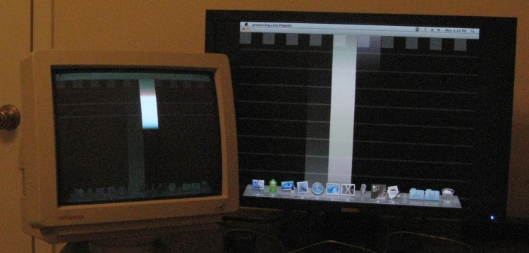
Setup the desktop to have them one on top of the other, stretched the RefreshRateMultiTool vertically so it spans on both screens. Then took some pictures.

From other threads I've read it seems that doing it like this will introduce error between the two screens because of how the video card refreshes.

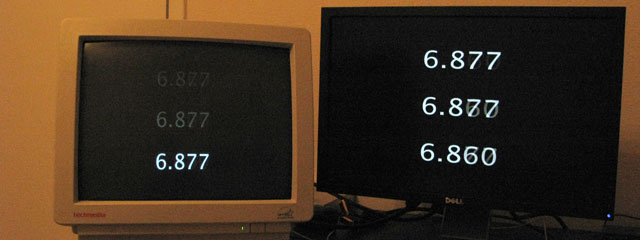
From what I can tell from the pictures the AW2310 is never more than a Bar behind. You can see it lighting up the pixels (almost like a grayscale bar from black to white) not far behind the CRT.

The one thing I'm not sure about is how on some of the pictures we get some yellow on the LCD. Ambient lights never changed for the duration of the picture taking.

Click HERE for all of the 286 pictures if you want to go through them and give us the analyzed data. (I did not feel like it lol... :D)

druneauaw2310bar10.jpg

druneauaw2310bar9.jpg

druneauaw2310bar8.jpg

druneauaw2310bar7.jpg

druneauaw2310bar6.jpg
 
Looks like you have come up with a way we can definitely measure the input lag on this display.

...but, we need to make a couple changes. First, what is that program? We need to run a program which simply runs the same timer (showing milliseconds or .xxx seconds) on both displays.

assuming that program you're using works like i think it does, in that it intentionally syncs frames to each displays refresh, then it won't do us much good for this test. Even if this is not the case, I dont have any information on what exactly it's trying to display..... we need to discrete #'s to work with.

Could you run a similar set of photographs with your same setup, this time with a timer program which displays ms stretched across both screens?

set1: ~100 photographs per your current setup.

set2: SWAP outputs on your video card (e.g. plug the CRT to the opposite DVI port, and swap it with the LCD) make sure the CRT is set as primary this time (if the LCD was primary last time.) Then run the same set of photographs.

The two sets will be necessary to eliminate the possibility of any primary / secondary or port by port lag.

I'm sure another forum member can point you to a good timing program; i'll check back later.


Edit: also, if you can, set your shutter speed a bit slower. 1/480 seconds would be good.
 
I've tried different timers and was never able to convice myself that they were doing the right thing. My main concern is that they "say" they are refreshing at xxhz (usually 100 or 1000) but I have no way of knowing if they are skipping numbers or not. Also, we would need a timer program which we could have two timers in one instance to minimize software lag.

I've thought about running two instances of the same program then just zero-ing the data, but then you don't know which instance gets refreshed first etc...

Those are the main reasons why I chose to test with RefreshRateMultitool. When you launch the program it detects the refresh rate then proceeds to switch bars at the refresh rate speed. This means that there is one white bar for every hz. Which is good because this is the smallest measurement we can measure anyway. Also, the program automatically re-sizes properly upon stretching the window. So it's easy to stretch vertically on multiple monitors (could easily do three with ati card). It could also allow us to measure with vertical and/or horizontal bars. Which could seperate vertical lag an horizontal lag (if such a thing exists).

You are right in saying that I should do multiple sets switching inputs and primary monitor setting on the computer.

1/480 would be a nice multiple of 120hz but my camera won't allow me. 1/500 is the closest increment. But I should have gone slower than 1/1250 to make things clearer (although we get to see the pixel transitions from white to black to white on the faster shutter speed)

I understand your concern in getting the same instance of the timer two times. I'm thinking just use one really big instance like http://www.xnotestopwatch.com/ and just stack the displays on top of eachother in extended desktop. Move the timer so that it's half way on each screen. We should be able to figure out what # each display is showing most of the time even if we can only see half on each. I think it would work. Take the pics and i'll extract the data, analyze and post the results.
 
Druneau, it's great that you done an input lag test using this technique. It's much better than using numeral-based timers and stopwatches, for so many reasons.

It's also good that you posted your full data set of 286 photos, because all five that you posted in this thread have tearing on the CRT (horizontal tearing) and all but one also have tearing on the camera (diagonal tearing). Your photos #137 through #277 were taken during a period when there was no tearing and are the only ones we should look at. Probably the ones right smack in the middle of that range are the best.

Many of the photos, including ones in the range 137-277, have "on-camera" tearing. Since your text overlay says "50D", you probably used a Canon 50D. The camera tearing would be from the focal plane shutter; since you tilted the camera 90 degrees, it's scanning right-to-left on the CRT rather than up-to-down, which is perfect — it prevents the rolling shutter effect from being lost in the scan pattern of the CRT & LCD and allows it to be measured. My measurements show that the camera scanned from the right to the left of the CRT screen in the time it took for the CRT to scan 21% of its height. Assuming the CRT spent about 6% of its time in vertical blanking (which is the default when I switch my CRT to 1024x768@120Hz; the modeline may or may not differ for you), it means your camera scanned across the CRT image in about 1.65 milliseconds; the photo is 17% wider than the CRT image, which would make that about 1.90 milliseconds to scan the full frame — 1/520 second, a longer time than the shutter speed (which your text overlay shows as 1/1250 second). This can be safely ignored when interpreting the photos, because the two monitors line up in the photo and the on-screen vertical bars nearly line up — and the measurements can be aligned to line up even better. (If you hadn't tilted the camera 90 degrees, and had taken landscape-orientation instead of portrait-orientation shots, it would be a big problem, so it's good you tilted it!)

So, I want to know how much lag there is between when the CRT scans a particular row of the screen and when the LCD just begins to fade from black to gray in the corresponding region. I'll look at photo #209 for this purpose. It appears that you cropped a bit from the top of the LCD in your photos, which is unfortunate, but I'll assume it's an insignificant crop. In which case the LCD is just beginning to fade to gray on the top of the rightmost bar in photo #209, whereas the CRT has already scanned down 37% of the way at that same moment. So that would correspond to an input lag of 2.9 milliseconds. However, the progress of the "descanning" of the previous bar on the LCD tells a different story; it resets from white to black much faster than it goes from black to white. So taking that into account, and picking a vertical coordinate between the grey-to-black of the previous bar being undrawn and the black-to-grey of the current bar being drawn, the LCD has probably scanned 16% of the way down (and taking into account rolling shutter on the camera in alignment with the horizontal coordinate in-between the two bars on the LCD image, the CRT seems to have scanned 39%, not 37%), meaning the input lag would only be (39%-16%)/106%/120Hz = 1.8 milliseconds. (The 106% is from a guess of 6% vertical blanking time.)

So here's some data points:
Photo #191: LCD=66%, CRT=87%, lag = 1.7 ms
Photo #192: LCD=73%, CRT=97%, lag = 1.9 ms
Photo #206: LCD=70%, CRT=96%, lag = 2.0 ms
Photo #209: LCD=16%, CRT=39%, lag = 1.8 ms
Photo #219: LCD=35%, CRT=58%, lag = 1.8 ms
Photo #232: LCD=46%, CRT=70%, lag = 1.9 ms

(Note: The above measurements did not take into account perspective correction on the CRT due to its deviating significantly from being parallel to the focal plane. The LCD appears to be rather close to being parallel to the focal plane and probably doesn't need perspective correction.)

Since the photos are JPEG-compressed with a quality too low to see detail in the really dark areas (where the LCD fades from dark gray to black) I can't get really precise measurements. That's probably why I'm getting fluctuations in my readings/interpretations of the photos (as well as the absence of perspective correction). But I'd say 1.85 milliseconds is a pretty good preliminary estimate of the input lag of your LCD. Taking measurements on a whole bunch of the photos might result in a more accurate number, with an quantified error bar, but it'd be better if you could take photos either in RAW format (.CR2) or at a very high-quality/larger JPEG, or PNG. And also, if you repeat this test, move the camera back a little farther (or remove the top text overlay) so you aren't cropping the top of the LCD! In fact removing that text overlay might be enough to reveal the top of the LCD even in the photos you already posted. (If a significant area of the LCD was hidden by that text overlay on top, then the true lag is even lower than 1.85 ms.)

If you still have the originals, please post some from the range in which there's no horizontal tearing on the CRT (from a phase mismatch between the two outputs from the video card), but in which there is diagonal tearing (from the camera's rolling shutter). (Strip the EXIF if you like, but please don't recompress the photos with lossy compression. If you took them in RAW format then please either post the .CR2 files or compress with a lossless format such as PNG.)

Now, if only someone had done a test like this on a recent-generation 30" 2560x1600 LCD, such as the 3008WFP, I might not have had to commit to the 3007WFP-HC in order to guarantee low input lag. (I still suspect the 30-inchers with scalers may have input lag just as low as the older ones without scalers, but it's just a hunch; there's still no data on this.)


Regarding the suggestions from other posters in this thread: No stopwatch program is going to offer such consistent, precise and accurate results. We're talking a range of 1.7 - 2.0 ms (mean = 1.85 ms, range = 0.3 ms, standard deviation = 0.104 ms), and that's from low quality JPEGs, using no perspective correction in the measurements. Furthermore, this number actually means something, whereas in most stopwatch-based input lag tests, you don't really know what was going on behind the scenes.
 
Last edited:
Nice analysis - maybe you could explain this to one of the big monitor review sites like digital vs :)
 
Wow, someone's using my tool. :eek: I feel honoured and I'm glad it was useful! :D Let me know if you need any changes done for better testing...

And meanwhile, I'm gonna actually read this thread. :D
 
I'm glad that some people can understand how this tool is a more accurate test than those timers (that are unsynchronized with the vertical refresh).

It's behaviour is very clearly defined. It displays a distinct image for every frame your monitor can display (i.e. by using v-sync).

Here's a visual explanation:

refreshratemultitool.gif

If you run it on two monitors in clone mode, you should be able to get a very precise difference in time between the two displays.
 
Last edited:
Hi shurcooL,

Thanks for making this tool. I do have a suggestion:

Allow RefreshRateMultitool to be started up with N windows (e.g., 2 or 3, instead of just 1) where the extra windows are slaved to the first window, i.e. showing exactly the same number and placement of bars, with synchronization to just one monitor's vsync. Allow the extra windows to be independently resized. Then the tool could be used on monitors of non-matching resolutions without using Clone mode (Clone mode has the potential problem in this situation of introducing extra lag on an LCD due to scaling from non-native resolution).

Druneau used the work-around of placing one monitor on top of the other (both logically and physically) and stretching the RefreshRateMultitool window across both monitors, but this technique has the downside of not filling the monitor with higher horizontal resolution. This isn't really a problem for measurement, but it is aesthetically displeasing.
 
That's a good suggestion, but I'm afraid it might be a little too difficult. I would have to use a different library to create windows with OpenGL context (or write Win32 code myself... ugh). Even then, ensuring all windows are 100% synchronized might not be trivial.

But I'll think about it... I'm just saying it's not a trivial change than I can do in 5 mins, unfortunately. :)
 
I'm glad that some people can understand how this tool is a more accurate test than those timers (that are unsynchronized with the vertical refresh).

It's behaviour is very clearly defined. It displays a distinct image for every frame your monitor can display (i.e. by using v-sync).

Here's a visual explanation:
If you run it on two monitors in clone mode, you should be able to get a very precise difference in time between the two displays.


Let me try to better explain why I feel this analysis with your software may not be valid.

  • Your software syncs to refresh rate. How would it handle then both monitors being a different refresh rate?
    How do you know the images are sent to each display at the exact same time?
  • Why do the images on the LCD appear not as sollid columns but rather as gradient shaded black to white or white to black? clearly the CRT display shows some part white/part black. This is due to tearing. But this is also evidence your software isn't working as you described. Also - if the tearing on the CRT is a result of your software syncing to the LCD refresh and attempting to display the same frames at the same time to the CRT (this would be a good thing for the validity of this measurment) it doesn't explain why the LCD images are gradient.
  • Assuming your program was working as described without the anomolies above, a non vsync'd timer program would still be a superior method as it would display the precise time "frozen in time" the last possible moment the CPU was able to modify data before it was sent to the monitor. This could very well mean in an extended desktop or clone mode that differences between the two displays timer outputs may be different than 1/refresh rate. e.g. 16.66666 ms or 8.3333333 ms, etc.

Barring more information (I'm going to do some testing myself with your software) I feel any conclusion relating to input lag measurments on an LCD will not be valid. This includes this test.
 
Hello okashira,

You bring up good points. You certainly need to understand all those things to properly interpret photographs of RefreshRateMultitool running on two monitors.

I expect that in almost all cases, the refresh rate will not be exactly the same on both monitors. However, it will in most cases be very close, for example, 59.89 Hz on one monitor and 60.03 Hz on the other. This will have the effect of making RefreshRateMultitool vsync perfectly to one of the monitors, and the other monitor will have tearing. The tearing mark will gradually float from the bottom to the top and wraparound back to the bottom, or vice-versa (from the top to the bottom, wrapping around back to the top). Just to make this clear: the tearing mark will take many, many frames (about half a minute at least) to float all the way from top to bottom or vice-versa. If you wait for the tearing to float off-screen (into the vertical blanking period of the monitor exhibiting tearing), and take photographs only during this period, you can safely ignore the mismatch in refresh rate — because during the length of time the tearing is off-screen, to a very good approximation the two monitors effectively have exactly the same refresh rate and are in effectively identical phase. (Of course if the monitors have very different refresh rates, like 59.07 Hz and 61.93 Hz, the data will be rubbish. Or even worse, 60 Hz on one monitor and 75 Hz on another — the data will be total rubbish.)

The images on the LCD have areas of gradient from white to gray to black because LCDs do not have instant response. That's what the "response time" in LCD specifications means: when the LCD applies voltage to a pixel that was previously black, it takes some time for it to become completely white (and vice-versa). The beauty of the vertical bars test, displayed by RefreshRateMultitool, is that it lets you clearly see this effect of LCD response time, and account for it. To measure input lag, you want to look at the exact spot where full white just begins to change back to black (i.e. becomes a slightly darker white), and full black just begins to become white (i.e., becomes a dark gray just slightly paler than black). This can result in very precise sub-frame measurements of input lag (sub-frame = with more precision than the length of a frame). To interpret this properly you must understand that both LCDs and CRTs refresh from the top to the bottom, with a small period of vertical blanking before repeating. In particular, you must understand how this refresh pattern interacts with the particular camera being used, when photograph both monitors "simultaneously", because most cameras also take time to scan from top to bottom.

Note that these same "anomalies" happen even when using a stopwatch/timer displayed on screen; they are not flaws in the RefreshRateMultitool software. The problem is, when using stopwatch/timer software, you can't even see the anomalies very well, so you end up missing a lot of data, even if the timer software is perfect. When you see two numeric time values blurring together in a photograph of timer software, this is a case where RefreshRateMultitool would in fact show you the entire gradient from white to black, whereas a piece of stopwatch/timer software will only show you two numbers blurring into each other (which is in many cases ambiguous).

So in short, the things you list as problems/anomalies are actually strengths of the RefreshRateMultitool software. If you understand how to interpret them, it will allow you to measure very precise values for input lag (and response time too, if you want to measure it).
 
Last edited:
Let me try to better explain why I feel this analysis with your software may not be valid.
MetaGenie has already covered a lot in his excellent response. Props man. :)

I will just add a few points.

Your software syncs to refresh rate. How would it handle then both monitors being a different refresh rate?
How do you know the images are sent to each display at the exact same time?
Keep in mind this tool was meant to be used with two monitors set to Clone mode (same res, same refresh rate). This gives you the advantage of being able to swap monitors and see if the results stay consistent. It's no different from any clock app out there. Instead of displaying time in numbers, it displays it using successive white vertical bars.

Why do the images on the LCD appear not as sollid columns but rather as gradient shaded black to white or white to black? clearly the CRT display shows some part white/part black. This is due to tearing. But this is also evidence your software isn't working as you described. Also - if the tearing on the CRT is a result of your software syncing to the LCD refresh and attempting to display the same frames at the same time to the CRT (this would be a good thing for the validity of this measurment) it doesn't explain why the LCD images are gradient.
Congrats! You've just discovered that LCDs are more similar to CRTs than you've thought (as did I, only after making this tool did I realize the following). LCD monitors too, refresh all pixels one row at a time, from top to bottom. At 60 hz, this is not done all at once/instantly every 16.67 ms, but rather _during_ those 16.67 ms. And because each pixel takes time to go from black to white or white to black, you see this effect captured.

Believe you me, the LCD _is_ trying to display nothing more than one vertical bar lit at a time (assuming v-sync is working). The reason you're seeing something else is due to its limitations (i.e. input lag, and white2black/black2white pixel response times, time taken to update all pixels to new frame).

Assuming your program was working as described without the anomolies above, a non vsync'd timer program would still be a superior method as it would display the precise time "frozen in time" the last possible moment the CPU was able to modify data before it was sent to the monitor. This could very well mean in an extended desktop or clone mode that differences between the two displays timer outputs may be different than 1/refresh rate. e.g. 16.66666 ms or 8.3333333 ms, etc.
I don't know. Personally, I think you get more information _with_ v-sync, because you know the exact frame that the monitor is trying to display.

Take a look at this picture. It had an exposure time of 1/60th of a second, and it captured the right time frame where the CRT on the right traced one frame, from top to bottom.

On the left, you see a LCD in Clone mode *trying* to display the same frame as the CRT does; yet it's showing something about 1 full frame in the past (with a bit of the new frame, and a bit of 2 frames ago blended in).
 
Last edited:
I annotated a couple of Druneau's photos:

druneauaw2310bar162anno.png

Druneau_AW2310_Bar_162_annotated_LCD.png

druneauaw2310bar232anno.png

Druneau_AW2310_Bar_232_annotated_CRT.png
 
Sorry for the delayed reply to the thread. Pretty busy week.

I've read through and there are some good points/explanations. I plan on setting up for a second round of pictures tomorrow night. I'll just make a list of things I should do/change from the first time to make sure I understood correctly. Here it is:

-Keep using RefreshRateMultitool (I've looked at clock softwares and the only way I'd do some extensive testing with one is if it was in direct3d/opengl and able to Vsync. If not we loose alot from the resulting captured pictures).
-User slower shutter speed (I will slow it down to around 1/500 so we see "better". I'll also setup better ambient light)
-Shoot raw or sraw (I shot small jpeg first time for unlimited burst... I basically did the 286 pictures at 6fps lol).
-Compress in PNG to keep data and keep native resolution
-Crop less (I was very aggressive with my first batch of pictures. I had not realized we needed more detail in order to calculate times with more precision. I see this now.)
-Ensure camera and screens are perfectly parallel. (I'll switch up to 200mm lens and setup where I have enough room. This should help minimize perspective distortion)
-Make 4 data sets of ~100 pictures. (Swap ports + Driver Display order. So CRT Primary+Port1, CTR Primary+Port2, CRT Secondary+Port1 and CRT Secondary+Port2)

Another small thing is that I purchased my CRT off a company I used to work for. I know they have two identical HP1130's sitting around. I'm very tempted to try and purchase one off of them to allow to test for Video card lag. (if this makes any sens and to determine if it's a constant phase difference?). The only Issue is that the job was left on less than perfect terms lol.. so some yelling could occur. But if it can help us a lot I could give it a shot.

If I left out anything I need to do/change let me know so I can do it right.
 
Don't forget to use Clone Mode and ensure the two displays are at the exact same refresh rate. The tool won't work right in extended desktop due to differences in the displays refresh (even if the differences are infintesimal e.g. due to uncertainties in the frequency generators ...)
 
Don't get too anal about the pic quality and alignment... no that important. None of that RAW / PNG jazz. Just get a large number at decent resolution.
 
Thinking more about it, do it in extended desktop mode as well, remembering to switch outputs just like you descripted.

Per MetaGenie's description, as long as I have the information relating to which display RRMT is syncing to, I can still calculate the lag. It will just require more data points and the analysis will be a bit more complicated.

Post the pics and I'll do the calcs.
 
Druneau, I've put your lines in orange italics with my replies in normal white (instead of using QUOTEs, because those take up more space).

-Keep using RefreshRateMultitool (I've looked at clock softwares and the only way I'd do some extensive testing with one is if it was in direct3d/opengl and able to Vsync. If not we loose alot from the resulting captured pictures).

Yes. Except that Vsync is only one of the problems with existing clock software programs. The other problem is that they cannot give you precise sub-frame measurements (which vertical bars can), even if vsynced perfectly.

-User slower shutter speed (I will slow it down to around 1/500 so we see "better". I'll also setup better ambient light)

Not a good idea. The input lag I measured from your last set of pictures was already on the order of 1/540 second (1.85 ms), so you should if anything be aiming for faster shutter speeds, not slower. At least stick with 1/1250.

And don't increase your ambient light levels! That would be a very bad thing. Ambient light creates glare on the monitor, which decreases the signal-to-noise ratio of the monitor's output — meaning that I will not be able to measure the threshold between black and dark gray as well as I would otherwise. It might even be a good idea to take one picture with full ambient light, just to give a reference for where the monitors' frames are, and then turn off the ambient light completely for the rest of the pictures (relying on the tripod to keep everything framed exactly the same).

-Shoot raw or sraw (I shot small jpeg first time for unlimited burst... I basically did the 286 pictures at 6fps lol).Sounds great. This would in fact be a perfect application for sRAW, if you decided that RAW would be too big.
-Compress in PNG to keep data and keep native resolution


Super-high-quality JPEG would probably just as good, and likely would result in smaller files. Much more information is lost in the conversion from RAW->RGB; comparably little is lost in an RGB->JPEG conversion of a digital camera photo, as long as a low JPEG compression ratio (i.e. high quality) is used and native resolution is kept.

I would like to see some of the original sRAW / RAW files so that I can use the linear levels to do some photometric calculations of LCD response time.

-Crop less (I was very aggressive with my first batch of pictures. I had not realized we needed more detail in order to calculate times with more precision. I see this now.)
-Ensure camera and screens are perfectly parallel. (I'll switch up to 200mm lens and setup where I have enough room. This should help minimize perspective distortion)
-Make 4 data sets of ~100 pictures. (Swap ports + Driver Display order. So CRT Primary+Port1, CTR Primary+Port2, CRT Secondary+Port1 and CRT Secondary+Port2)


Yes to all three of these. :) It might be overkill, and I expect all four configs will yield the same timings, but OTOH we might learn something unexpected.

Another small thing is that I purchased my CRT off a company I used to work for. I know they have two identical HP1130's sitting around. I'm very tempted to try and purchase one off of them to allow to test for Video card lag. (if this makes any sens and to determine if it's a constant phase difference?). The only Issue is that the job was left on less than perfect terms lol.. so some yelling could occur. But if it can help us a lot I could give it a shot.

I doubt that it is possible to measure video card lag using photography. It's probably on the order of microseconds or less, and would require an oscilloscope. But it can't hurt to try. Or maybe it can, lol? (your ears, that is)

If I left out anything I need to do/change let me know so I can do it right.

There is one important thing you left out in the list — wait until the tearing drifts off-screen before taking a round of photos (or better yet, start taking photos just as it is about to drift off from the top or bottom edge of the screen).

Also, if you can give me the "modelines" that your LCD and CRT are being driven at, it'd make my calculations much more precise. You might need to install PowerStrip to be able to see this information.
 
I still feel that RRMT method is flawed. "Sub frame" lag measurments are not even nessisary with sufficient datapoints. The average will still converge to a sub-frame lag value if that is the case. I am still having trouble wrapping my head around the concept that LCD's draw their screens with a horizontal scan rate like CRTs. I have NEVER heard of this in any case, nor seen any kind of evidence of it from any photograph or usage until Dreanu's pictures in the OP.

There are still issues with attempting to calculate lag on a system where it's synced to the refresh rate on one screen, but not the other. Again, this can probably be account for in the analysis, but why take the chance?

I'd like to see RRMT written so that it's not synced to vsync, but rather flashes the bar at 1000Hz. Increase the number of bars to 100 (so that every 1/10th a second it will start again on the left) This would better allow for measurment between displays of different refresh rates, including extended desktop as well as clone.

In any case, I'll be satisfied when we have SOMTHING objective! :)
 
I am still having trouble wrapping my head around the concept that LCD's draw their screens with a horizontal scan rate like CRTs. I have NEVER heard of this in any case, nor seen any kind of evidence of it from any photograph or usage until Dreanu's pictures in the OP.
I know it's a little hard to believe, but it seems to be true. I, too, only found this out after testing my own tool.

But it makes sense if you think about it. What are the alternatives? That at 60 hz, every 16.67 ms the LCD suddenly updates the "target" pixel colours of _EVERY SINGLE PIXEL_ on its screen simultaneously? How would that even be physically possible? Each "frame" at 1920x1200x24 bit colours is 6.59 megabytes of data!

Instead, it takes the LCD 16.67 ms (ok, slightly less) to update all of its 1920x1200 or whatever pixels to the "target" colour, by scanning through each pixel, one row at a time (which is probably also scanned from left to right, one pixel at a time), from top to bottom.

Of course, after each pixel has been updated to a target colour, it takes some time (i.e. pixel response time) to change itself into the new colour.

Edit: Food for thought. Think about why you get "tearing" on an LCD with v-sync off. It's precisely because it updates pixels on a row by row basis, not everything at once.
 
Last edited:
okashira said:
I still feel that RRMT method is flawed. "Sub frame" lag measurments are not even nessisary with sufficient datapoints. The average will still converge to a sub-frame lag value if that is the case. I am still having trouble wrapping my head around the concept that LCD's draw their screens with a horizontal scan rate like CRTs.
You keep saying these methods are flawed, but then you recommend methods that are more flawed:

okashira said:
I understand your concern in getting the same instance of the timer two times. I'm thinking just use one really big instance like http://www.xnotestopwatch.com/ and just stack the displays on top of eachother in extended desktop. Move the timer so that it's half way on each screen. We should be able to figure out what # each display is showing most of the time even if we can only see half on each. I think it would work. Take the pics and i'll extract the data, analyze and post the results.
This would be very flawed because I don't see any guarantee that XNote Stopwatch will update often enough to be accurate, and you're not taking into account that the top of the screen will update before the bottom of the screen, so the bottom monitor would have an advantage even if both monitors refreshed at the same time, which isn't guaranteed either.

okashira said:
Assuming your program was working as described without the anomolies above, a non vsync'd timer program would still be a superior method as it would display the precise time "frozen in time" the last possible moment the CPU was able to modify data before it was sent to the monitor.
No, it wouldn't. You're assuming the timer would update as fast as possible, which isn't the case with most timers. Even if the timer were to update as fast as possible, when the timer updates while that part of the screen is being refreshed, there would be tearing with pieces of different numbers being shown.

You're also not taking into account that monitors draw from top to bottom. The vsynced bars program allows you to see where each monitor is refreshing. To do that with a timer, you'd have to duplicate the timer on multiple parts of the screen, and to do that without vsync, you'd have to update all the timers as fast as possible. Prad has a tool that does exactly that, but it's useless because the numbers tear and blur together, making them impossible to read, and their own reviewers don't even know how to read the results properly.

Using vsync avoids those problems. I've been using a hybrid of those two methods, displaying a vsynced timer in multiple parts of the screen, but I also use a splitter, so the results are always consistent. This method clearly shows that LCD monitors also refresh from top to bottom:

2209wa-crt-lag-bottom.jpg


That was with a splitter, which eliminates the possibility that each monitor is getting something different. The top number on the LCD is almost fully updated because it was refreshed earlier than the bottom number, which is just starting to update. You can tell this is due to refreshing and not the program because the CRT is showing the same number the whole way through.

The vsynced bars program is simply a more precise version of that test. It would be preferable to use the bars program with a splitter, but it can be used without one as long as the refresh rates are close and you wait for the output to be synchronized, as MetaGenie as suggested.

I used something similar once:

ds-lag1.jpg


That was also with a splitter, so you can eliminate clone mode and other anomalies suggested in this thread.
 
I should also add, there are three main reasons why most lag tests are flawed:

1. Most timers are not synchronized with the refresh rate and are not guaranteed to update at any particular interval. Flash-based timers are the worst offenders, especially that flatpanels.dk timer that people keep using. Using a program with vsynced output solves this problem.

2. Most tests don't take into account that monitors refresh from top to bottom. Duplicating the timer on multiple parts of the screen or using vertical bars solves this problem.

3. Clone mode is not guaranteed to update both displays at the same time. Using a splitter solves this problem.

If you solve all three problems, you will always get consistent results.
 
I guess the main reason we are in this thread is for the crop of 120hz lcd's that are being released. We are just trying to get consistent results (or as close as we can) without being physically able to clone or split a signal. We can't clone/split because we don't have CRT's that do 1920x1080@120hz.
 
ToastyX, how did you use a splitter to route output to a CRT and an LCD?

I'm guessing you used the LCD's RGB analog input. If so, this would not work on LCDs that lack analog input. It also implies an assumption that an LCD will exhibit the same lag on its analog (RGB / VGA) input that it does from its digital (DVI) input — but I would think that the analog input could potentially experience more lag due to analog-to-digital conversion and synchronization in the LCD's circuitry. Has this ever been tested?

Of course, one could use a DVI splitter and compare an LCD to another LCD that's already been compared to a CRT with known results, but this compounds upon any error that was in the original test. It also creates the complication (and potentially extra error) of having two sources of "response time" instead of just one.

What measurement did you get out of the vertical bars test pictured in your post?
 
Last edited:
But it makes sense if you think about it. What are the alternatives? That at 60 hz, every 16.67 ms the LCD suddenly updates the "target" pixel colours of _EVERY SINGLE PIXEL_ on its screen simultaneously? How would that even be physically possible? Each "frame" at 1920x1200x24 bit colours is 6.59 megabytes of data!

Don't think about it too hard. Plasma screens update all at once. They do seem to have issues with the blue phosphors being faster, though.

The Prad tool would be more useful if it changed columns for for the numbers every 10ms.
 
Last edited:
MetaGenie said:
ToastyX, how did you use a splitter to route output to a CRT and an LCD?

I'm guessing you used the LCD's RGB analog input. If so, this would not work on LCDs that lack analog input.
That's correct. I test against a CRT using a VGA splitter, and I test against other LCD monitors using a DVI splitter.

MetaGenie said:
It also implies an assumption that an LCD will exhibit the same lag on its analog (RGB / VGA) input that it does from its digital (DVI) input — but I would think that the analog input could potentially experience more lag due to analog-to-digital conversion and synchronization in the LCD's circuitry. Has this ever been tested?
I don't have any hard evidence, but several factors lead me to conclude there isn't a significant difference on most monitors:

Every monitor I've tested lags near frame boundaries +/- 3 ms, so I think of lag in terms of number of frames. I haven't seen any half-frame lags, although it may appear that way in some pictures due to response times, but if the number has already started to come in, I don't consider that part of the lag.

I've found I can feel a difference as small as one frame at 60 Hz, even to the point where I can tell the mouse cursor lags more at the bottom of the screen than at the top when using a hardware cursor, but not when using a software cursor. That tells me the hardware cursor is updated between refreshes, while a software cursor can update during a refresh as long as the output is not vsynced. I've found the difference is easier to notice on monitors that have at least two frames of lag, since the lag at the bottom of the screen just adds to the existing lag. Windows XP lets you disable the hardware cursor by moving the display troubleshooting slider one notch to the left. I don't think you can disable the hardware cursor in Windows 7 or Vista while using Aero, but it wouldn't matter anyway since the output is vsynced. At higher refresh rates, the lag difference between the top and bottom becomes smaller.

On monitors where I have tested VGA, I don't feel a significant difference in lag between DVI and VGA. That means if there is a difference, it would have to be less than one frame, and since I haven't seen any half-frame lags, it's most likely less than 5 ms.

I have also cross-tested LCD monitors against other LCD monitors. So far, I have not encountered any major inconsistencies. I think the NEC EA231WMi might be 2-3 ms slower over VGA than over DVI, but that's not significant enough for me to care about, and I don't even use VGA anyway.

MetaGenie said:
Of course, one could use a DVI splitter and compare an LCD to another LCD that's already been compared to a CRT with known results, but this compounds upon any error that was in the original test. It also creates the complication (and potentially extra error) of having two sources of "response time" instead of just one.
I've found when testing two LCD monitors against each other, most of the time the difference is an exact number of frames, so if I have a known reference, I can easily determine the lag. Response time is hardly a factor unless you want to consider 1-3 ms differences.

MetaGenie said:
What measurement did you get out of the vertical bars test pictured in your post?
Looks like about 3 ms.
 
Druneau said:
I guess the main reason we are in this thread is for the crop of 120hz lcd's that are being released. We are just trying to get consistent results (or as close as we can) without being physically able to clone or split a signal. We can't clone/split because we don't have CRT's that do 1920x1080@120hz.
Prad's method was an attempt to solve that problem so that you don't have to worry about the output being synchronized on both monitors. Their method requires figuring out what the latest number is on each monitor, which will be in different positions if the output is not synchronized. That would be great if you could only read the numbers.

In cases where using a splitter is not possible, doing what MetaGenie suggested by waiting for the output to be synchronized seems to be the best option.
 
Every monitor I've tested lags near frame boundaries +/- 3 ms, so I think of lag in terms of number of frames. I haven't seen any half-frame lags, although it may appear that way in some pictures due to response times, but if the number has already started to come in, I don't consider that part of the lag.
Interesting. Is there even a single monitor you've tested that broke this rule?

Can you give me an example of one that was -3 ms (or anything significantly negative) from a frame boundary? Did you notice any correlation between sub-frame offset and LCD technology (TN, IPS, VA)?

When I tested my 3007WFP-HC against my GDM-FW900, I measured an input lag of about 0.2 ms. That's the only input lag test I've done myself.

BTW, I agree that any lag of 5 ms or less is not significant enough to care about. However, I still think that it's worthwhile to measure input lag with much more precision than that, because many people use it as a major factor in their choice of monitor. If all else is equal, then input lag is the only thing left to compare — and the current numeric timer based tests are so random that they unfairly bias choices towards monitors which randomly happened to get lower numbers in digitalversus.

MetaGenie said:
What measurement did you get out of the vertical bars test pictured in your post?
Looks like about 3 ms.
Agreed, it looks like 3.1 - 3.2 ms.
 
Last edited:
MetaGenie said:
Interesting. Is there even a single monitor you've tested that broke this rule?

MetaGenie said:
Can you give me an example of one that was -3 ms (or anything significantly negative) from a frame boundary? Did you notice any correlation between sub-frame offset and LCD technology (TN, IPS, VA)?
Every monitor I've tested has been close to the frame boundary.

I originally wanted to say + 0-3 ms, but the NEC 2490 and 2690 are actually slightly ahead of two frames. Those are the only negatives I've seen.

I haven't noticed anything specific to any particular LCD technology.


MetaGenie said:
When I tested my 3007WFP-HC against my GDM-FW900, I measured an input lag of about 0.2 ms. That's the only input lag test I've done myself.

BTW, I agree that any lag of 5 ms or less is not significant enough to care about. However, I still think that it's worthwhile to measure input lag with much more precision than that, because many people use it as a major factor in their choice of monitor. If all else is equal, then input lag is the only thing left to compare — and the current numeric timer based tests are so random that they unfairly bias choices towards monitors which randomly happened to get lower numbers in digitalversus.
I think it's worth testing also, but when testing against a CRT monitor, it's hard to determine if a slight difference is due to analog-to-digital conversion, response times, upscaling, or other factors because the difference is too small, so I don't worry about it. If the difference was significant enough, I'd be able to tell where the lag is coming from.

When testing two LCD monitors against each other, the playing field is more level, so if I encounter a slight difference, I know one monitor is slightly ahead of another.
 
ToastyX, have you published your input lag measurements? It'd be nice to see them all in one page.

Actually, a single page with links to your posted reviews would be quite nice.
 
Last edited:
Some results I never published, and I didn't do extensive testing of older monitors. All I cared about was if there was more or less lag, which was easy to verify simply by dragging a window up and down between two monitors. Once I came up with the vsynced three timer method and started testing LCD monitors against each other, that's when I realized they lagged close to frame boundaries because the difference was always close to an exact number of frames.

Here are some of the results:

The DoubleSight DS-263N is the monitor shown in the bars test above. When tested against the Dell 2209WA and the NEC EA231WMi, it seems to be slightly slower at the top of the screen for some reason, maybe due to the scaler.

Dell 2209WA: 0 frames
vs. CRT: 0-2 ms behind
vs. DoubleSight DS-263N: 1-2 ms ahead, slightly more ahead at the top of the screen
Review: http://hardforum.com/showpost.php?p=1034016351
Lag results: http://hardforum.com/showpost.php?p=1034028590

NEC EA231WMi: 0 frames
vs. CRT: 1-3 ms behind
vs. Dell 2209WA: about the same
vs. DoubleSight DS-263N (not shown): 0-1 ms ahead, slightly more ahead at the top of the screen
Review: http://hardforum.com/showpost.php?p=1034824130
Lag results: http://hardforum.com/showpost.php?p=1034865808

Samsung F2380: 0 frames
vs. CRT: Didn't test
vs. Dell 2209WA: about the same, maybe 1-2 ms behind, hard to tell due to slow response time
Review + lag results: http://hardforum.com/showpost.php?p=1034329391

HP DreamColor LP2480zx: 1 frame
vs. CRT: Didn't test
vs. DoubleSight DS-263N: 1 frame behind
Review + lag test: http://hardforum.com/showthread.php?t=1366545
I mentioned 20-25 ms in the review, but it looks more like 18-20 ms (1 frame + 3 ms max).

EIZO HD2441W: 2 frames
vs. CRT: Didn't test
vs. 23" Apple Cinema Display: 2 frames behind
Review + lag test: http://hardforum.com/showpost.php?p=1031371458
I mentioned 40 ms in the review, but it looks more like 34-36 ms (1 frame + 3 ms max). I mentioned the 23" Apple is about half a frame behind a CRT, but that was before I ever tried the bars test, so that included some of the response time. The 23" Apple is really about the same as the DoubleSight DS-263N and Planar PX2611W, as shown below:

DoubleSight DS-263N: 0 frames
vs. CRT - 3 ms behind
Review: http://hardforum.com/showpost.php?p=1032187513
Lag test: http://hardforum.com/showpost.php?p=1032188597
Bars test: http://hardforum.com/showpost.php?p=1032194456

Planar PX2611W: 0 frames
vs. CRT - 3 ms behind
vs. 23" Apple - about the same
http://www.toastyx.net/planar-lag-10.jpg
http://www.toastyx.net/planar-lag-11.jpg
http://www.toastyx.net/planar-lag-12.jpg
http://www.toastyx.net/apple-planar-lag-1.jpg
http://www.toastyx.net/apple-planar-lag-2.jpg
http://www.toastyx.net/apple-planar-lag-3.jpg

The DoubleSight DS-263N and the Planar PX2611W are basically the same monitor with different branding, so the results can apply to both monitors.

I know I've done a few more than these, but I don't have the pictures handy. Some of the tests should also be redone for better precision.
 
Yes. Except that Vsync is only one of the problems with existing clock software programs. The other problem is that they cannot give you precise sub-frame measurements (which vertical bars can), even if vsynced perfectly.

You make an excellent point on the ability to make sub frame lag measurments using vertical bars. However, this is of course assuming that this "one line at a time" phenomena with LCDs is consistant and indeed repeats as predicted; that is, it transitions from the last line on one frame to the first line on the next frame with no delay. If there is a delay here, what is it? without this value, it's not much use. Is this effect consistant with all LCD's?

The problem Vsync is what results from the comprimises that must be made between software, hardware, drivers and the OS to create "vsync." Double Buffering, Frame Dropping...... When a frame is completed by the CPU and video card, is it displayed immediatly, as in the rendering process is programed in such a way that it will intentionally complete "immediatly prior to" the next frame rendering by the monitor? Or is the frame made available at some random interval prior to the display being ready to display it? Can this question be answered by addressing any possible role that ATI/Nvidia's drivers, Microsofts graphics engine may play in the process?

If the answer to the 2nd question is YES, then how can you know when a particular frame was rendered prior to being sent to the monitor? If you can't, then using the displayed result to calculate input lag is useless.

Not a good idea. The input lag I measured from your last set of pictures was already on the order of 1/540 second (1.85 ms), so you should if anything be aiming for faster shutter speeds, not slower. At least stick with 1/1250.

And don't increase your ambient light levels! That would be a very bad thing. Ambient light creates glare on the monitor, which decreases the signal-to-noise ratio of the monitor's output — meaning that I will not be able to measure the threshold between black and dark gray as well as I would otherwise. It might even be a good idea to take one picture with full ambient light, just to give a reference for where the monitors' frames are, and then turn off the ambient light completely for the rest of the pictures (relying on the tripod to keep everything framed exactly the same).

Agreed on lighting. Ambient light doesn't help us.

Shutter speed should be set slow enough such that in no situation would the CRT's display of the timer is unreadable; and no faster. If, in the end, we're trying to measure the difference between 1 and 2 ms of lag, this will come out of an analysis done with images at slower shutter speeds. The law of averages says so.

Also, between 1 and 2 ms.... Let's just say I'll be buying one of these monitors if that's what it comes down to.

We need to concentrate on eliminating sources of error before we we work to improve the precision of the measurment.

I doubt that it is possible to measure video card lag using photography. It's probably on the order of microseconds or less, and would require an oscilloscope. But it can't hurt to try. Or maybe it can, lol? (your ears, that is)

No need to bother measuring video card port/port lag as long as you're providing datasets from when outputs are switched. Any such lag will be averaged out.

There is one important thing you left out in the list — wait until the tearing drifts off-screen before taking a round of photos (or better yet, start taking photos just as it is about to drift off from the top or bottom edge of the screen).

See my points above about Vsync. The position of the tearing on the non synced screen is irrelevant (as long as we have info from all possible situations, here being 1 with RRMT synced to the LCD and 1 with RRMT synced to the CRT. It would be still be much better yet to eliminate VSYNC.
 
I know it's a little hard to believe, but it seems to be true. I, too, only found this out after testing my own tool.

But it makes sense if you think about it. What are the alternatives? That at 60 hz, every 16.67 ms the LCD suddenly updates the "target" pixel colours of _EVERY SINGLE PIXEL_ on its screen simultaneously? How would that even be physically possible? Each "frame" at 1920x1200x24 bit colours is 6.59 megabytes of data!

Instead, it takes the LCD 16.67 ms (ok, slightly less) to update all of its 1920x1200 or whatever pixels to the "target" colour, by scanning through each pixel, one row at a time (which is probably also scanned from left to right, one pixel at a time), from top to bottom.

Of course, after each pixel has been updated to a target colour, it takes some time (i.e. pixel response time) to change itself into the new colour.

Edit: Food for thought. Think about why you get "tearing" on an LCD with v-sync off. It's precisely because it updates pixels on a row by row basis, not everything at once.

Someone else has already shown that digital displays can update the entire screen at once just fine. I'm still not sure if relying on this phenomena is a reliable method. Also, tearing is completely independent of the phenomena .... are plasma's immune to tearing ?
 
You keep saying these methods are flawed, but then you recommend methods that are more flawed:

Look into the benefits of using constructive critisim. :)

This would be very flawed because I don't see any guarantee that XNote Stopwatch will update often enough to be accurate, and you're not taking into account that the top of the screen will update before the bottom of the screen, so the bottom monitor would have an advantage even if both monitors refreshed at the same time, which isn't guaranteed either.

I think it's pretty silly to assume a program will not "update often enough" yet rely on the "repeatability" of vsync, which is highly questionable, IMO.

You have a point on top vs. bottom of the screen. Timers on top, bottom and middle would only offer a benefit.

No, it wouldn't. You're assuming the timer would update as fast as possible, which isn't the case with most timers. Even if the timer were to update as fast as possible, when the timer updates while that part of the screen is being refreshed, there would be tearing with pieces of different numbers being shown.

Nothing wrong with tearing. Those results can be taken into account. And why assume a timer can't update fast enough???? I think my system can run a quake timedemo at 1000Hz, I'm sure a timer program can do the same. Sure, I agree, the code and/or performance of the timer needs to be validated.

You're also not taking into account that monitors draw from top to bottom. The vsynced bars program allows you to see where each monitor is refreshing. To do that with a timer, you'd have to duplicate the timer on multiple parts of the screen, and to do that without vsync, you'd have to update all the timers as fast as possible. Prad has a tool that does exactly that, but it's useless because the numbers tear and blur together, making them impossible to read, and their own reviewers don't even know how to read the results properly.

Well, yes, but I never said I wasn't going to take top to bottom drawing into account in my analysis. Not really nessisary to have multiple timers top to bottom, but it would not hurt.

Using vsync avoids those problems. I've been using a hybrid of those two methods, displaying a vsynced timer in multiple parts of the screen, but I also use a splitter, so the results are always consistent. This method clearly shows that LCD monitors also refresh from top to bottom:

Using vsync causes other problems which completely invalidate any possibllity of avoiding the original problems, IMO.

That was with a splitter, which eliminates the possibility that each monitor is getting something different. The top number on the LCD is almost fully updated because it was refreshed earlier than the bottom number, which is just starting to update. You can tell this is due to refreshing and not the program because the CRT is showing the same number the whole way through.

The vsynced bars program is simply a more precise version of that test. It would be preferable to use the bars program with a splitter, but it can be used without one as long as the refresh rates are close and you wait for the output to be synchronized, as MetaGenie as suggested.

I used something similar once:

ds-lag1.jpg


That was also with a splitter, so you can eliminate clone mode and other anomalies suggested in this thread.

I strongly disagree with using a VGA splitter for an LCD lag test. I want the LCD to be tested in the mode I'll be using it in (native res, digital source) not in a mode with requires it to scale, perform A/D conversion, who knows what else.

Sure, it elimnates video card port lag, but so does switching ports. How can you draw any conclusion on the LCD's digital performance from these tests?
 
I should also add, there are three main reasons why most lag tests are flawed:

1. Most timers are not synchronized with the refresh rate and are not guaranteed to update at any particular interval. Flash-based timers are the worst offenders, especially that flatpanels.dk timer that people keep using. Using a program with vsynced output solves this problem.

2. Most tests don't take into account that monitors refresh from top to bottom. Duplicating the timer on multiple parts of the screen or using vertical bars solves this problem.

3. Clone mode is not guaranteed to update both displays at the same time. Using a splitter solves this problem.

If you solve all three problems, you will always get consistent results.

Again, I disagree with your points 1.) and 3.)
  • Vsync bad
  • VGA / Splitter bad
 
I'll be awaiting Druneau's 2nd set of images. Let's not draw this out. Post some data!! :D
 
okashira said:
You make an excellent point on the ability to make sub frame lag measurments using vertical bars. However, this is of course assuming that this "one line at a time" phenomena with LCDs is consistant and indeed repeats as predicted; that is, it transitions from the last line on one frame to the first line on the next frame with no delay. If there is a delay here, what is it? without this value, it's not much use. Is this effect consistant with all LCD's?
Great, let's just make this more complicated! :D

There is a slight delay, but that applies to both LCD and CRT monitors. The delay depends on how many lines of vertical blanking there are, which includes the front porch, sync width, and back porch. During the vertical blanking period, nothing is updating on the screen. At exactly 60 Hz, each refresh always takes 16 ⅔ ms, which includes the blanking period.


For example, a standard 1080p 60 Hz signal has 40 lines of vertical blanking:

1080 + 40 = 1120
40 / 1120 * 16 &#8532; ms = approximately 0.595 ms <- that's the delay


Another example, a standard 1920x1200 60 Hz signal with reduced blanking to fit within DVI bandwidth normally has 34 lines of vertical blanking:

1200 + 34 = 1234
34 / 1234 * 16 &#8532; ms = approximately 0.459 ms <- that's the delay


okashira said:
The problem Vsync is what results from the comprimises that must be made between software, hardware, drivers and the OS to create "vsync." Double Buffering, Frame Dropping...... When a frame is completed by the CPU and video card, is it displayed immediatly, as in the rendering process is programed in such a way that it will intentionally complete "immediatly prior to" the next frame rendering by the monitor? Or is the frame made available at some random interval prior to the display being ready to display it? Can this question be answered by addressing any possible role that ATI/Nvidia's drivers, Microsofts graphics engine may play in the process?

If the answer to the 2nd question is YES, then how can you know when a particular frame was rendered prior to being sent to the monitor? If you can't, then using the displayed result to calculate input lag is useless.
That's why I prefer to use a vsynced timer. The timer will display the time when the frame started rendering. At 60 Hz, there should always be a 16-17 ms difference between two frames, which my pictures always show.


okashira said:
Someone else has already shown that digital displays can update the entire screen at once just fine. I'm still not sure if relying on this phenomena is a reliable method.
I have yet to see an LCD monitor that updated all at once, but even if it did, it would be obvious because the bars program would clearly show it. There would be no gradients.

The reason monitors update from top to bottom is because that's the way the video signal is received. For a display to update all at once, it has to buffer the entire image first, which means non-vsynced timers would be all wrong because the contents of the frame buffer are sent from top to bottom, so the timer at the top of the screen will show an earlier time even if the display updated all at once.


okashira said:
I think it's pretty silly to assume a program will not "update often enough" yet rely on the "repeatability" of vsync, which is highly questionable, IMO.
It's not an assumption. I constantly see people use programs that don't update often enough to get reliable results, while vsync has always shown consistent results when both displays are synchronized.


okashira said:
Nothing wrong with tearing. Those results can be taken into account.
Not if you can't read it! That's the biggest problem with Prad's tool. The point where the refresh is happening can't be reliably determined. The bars program shows you the exact point where the refresh is happening very clearly.


okashira said:
And why assume a timer can't update fast enough???? I think my system can run a quake timedemo at 1000Hz, I'm sure a timer program can do the same. Sure, I agree, the code and/or performance of the timer needs to be validated.
My point is most of the timers people are using don't update often enough. Prad's tool is the only one I know that's fast enough.


okashira said:
I strongly disagree with using a VGA splitter for an LCD lag test. I want the LCD to be tested in the mode I'll be using it in (native res, digital source) not in a mode with requires it to scale, perform A/D conversion, who knows what else.
I understand your concern about VGA, but A/D conversion is negligible on every monitor I've tested, and if I run into a case where it isn't negligible, I will notice it because I will feel the lag and the results won't be consistent when cross-tested with another monitor with a known amount of lag.

I have also used a DVI splitter to test different LCD monitors with the same native resolution against each other to eliminate scaling issues.

In the cases where the native resolutions didn't match, I tested both ways: each monitor at their native resolution with the other scaling. I did that with the NEC EA231WMi vs. the Dell 2209WA and there wasn't a difference either way.

I do see the problem with using splitters and non-native resolutions, but that hasn't caused a significant impact on the results.


Conclusion

I don't know. Do we need a new method? Prad's tool has the right idea but a bad implementation. We need something more precise and readable.
 
Back
Top