Accuracy of temp sensors

Top Nurse

Supreme [H]ardness
Joined
Nov 4, 2003
Messages
7,344
This subject has come up lately so I thought I would start a new thread on it.

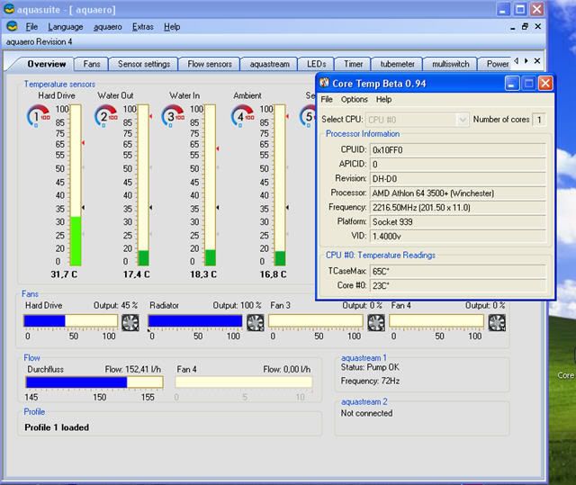
What I am trying to do is to ascertain the accuracy of my temp sensors I use in my Aquaero. I checked the AC website and they don't even list the tolerance of the sensors they sell (not a good sign). So what I want to know is if I measure the temp of the water right next to where the temp sensor is can I be reasonably sure that the temps are being reported correctly. I figured to go buy a Fluke 179 multi-meter because I want a good one (My analog Radio Shack MM died after 30 years service) and it also has a temp probe capability. The sensor I figured to get is the 80PK-22 Alternatively I also though of getting a lab grade mercury immersion thermometer and just sticking it in the reservoir through one of the top holes:


FFI_265_A.jpg


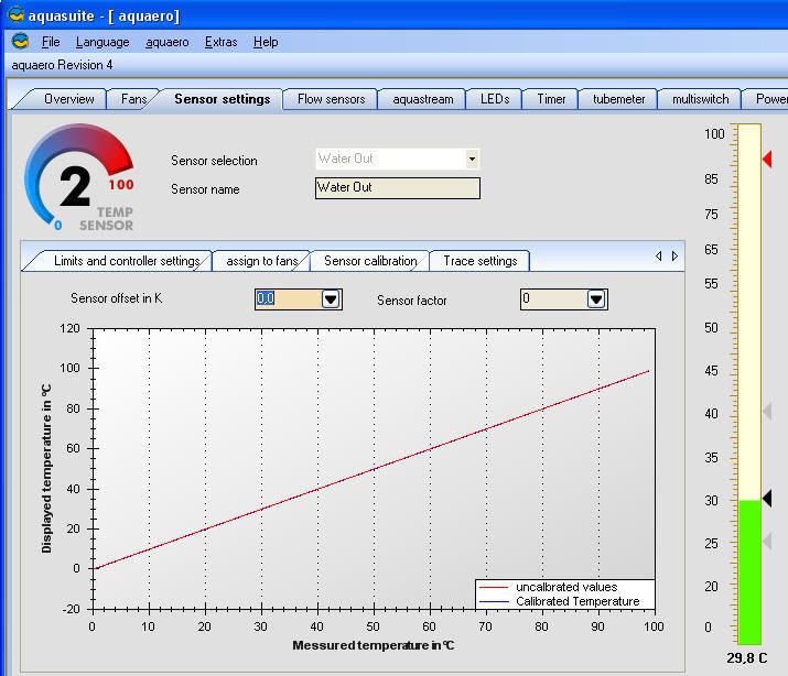
The Aquaero does allow me to make changes to the sensor settings to account for different sensors and I think this is the screen that does it:


TempCalibration.jpg


So what is the best way to go about this? Is the Fluke overkill?
 
this is based on the physical fact that ice melts at 32 deg F 0 deg C and if done carefully should be pretty accurate if you are anywhere near sea level.


Materials:
2 large (16 oz or bigger) Styrofoam coffee cups with a lid that has the "sipping" flap and a long stirrer or straw.
2 old style ice cube trays (clean)
1 gal distilled water.

freeze up two trays of distilled water ice.
while they are freezing keep the rest of the distilled water in the fridge.

When you have solid ice:

nest the coffee cups inside each other, we will now just call this the "cup".
fill cup 3/4 full of our ice. shake the cup, get the ice packed in there. We need some room at the top of the cup but the more ice the better. If you want to crush the ice and can do it without getting it contaminated - go for it.
fill just to top of ice with cold distilled water.
Stir for at least 1 min and let it sit for 5 min with lid on.
Remove lid
Stir for 1 min.
drop your temp sensor to just below the surface of the water let the wire come out of the "sipping" hole in the top. Putting your stirring utensil through the same hole (with the lid on) gently stir.

You should read 32F 0C.

the longer you wait while there is still a significant about of ice floating about the more accurate you will be and stirring is critical too. Do several measurements, with the double insulated cups the ice should last a good while.

Hint.
Boiling water at sea level is 100C


Warning some sensors are not made to take such extremes. The ice bath is fairly safe. The boiling water could damage or melt plastics.
 
Yes on the Kelvin and the Pacific Ocean is about 100 yards away. The Aquaero manual says that internal formula used to calculate temps is:

237 + Offset -(44,15-Factor) * In (measured value) (output is value in C) if that makes any sense.
 
Yes on the Kelvin and the Pacific Ocean is about 100 yards away. The Aquaero manual says that internal formula used to calculate temps is:

237 + Offset -(44,15-Factor) * In (measured value) (output is value in C) if that makes any sense.

OUCH !!! 237 (the number I was worried about finding) is the correction factor between kelvin and celcius, and I THINK the only other thing we need is the "offset", I hope so anyway because I have absolutley no clue what "-(44,15-Factor)" that could be and "* in (measured value)" will be what the sensor is reading and that is a given.

Kelvin and Celcius use the same amount of temp change per degree, Kelvin just starts at absolute zero so hopefully if your sensor reads 34C in the ice bath we just put "-2" in the offset.

LOL but the lab thermo might be a easier (but not as much "Mr Wizard" fun) way.
 
I will try this out tomorrow if I don't go to work. But how does measuring the temp at 0 C make sure that the temp is reading correctly at 28-40 C? Also where can I get thermistors that look like this that are accurate to + or - 0.1 C?


ACThermistor.jpg
 
I think we are missing the point here somewhere. In my setup, I have 10 sensors in my computer and 4 in my external waterbox. Perhaps the most "useful" (or "accurate") ones are physically in the water loop and my "ambient" air sensors. The remaining sensors are on heat sinks, external case of my HD's, etc.

In my case, I know I am not getting an accurate reading of the object I am trying to get a temperature from. As long as the sensor provides a reasonable accurate reading (read: calibrated), all I am looking for are delta temps. I use this information to control the speeds of the fans in my 2 boxs. In this context, they are doing exacting what they need to do.

Even if I could mount them directly to the IHS of the CPU and GPU, how close are they an "actual" component temperature? If I want a "real" temperature of the GPU and CPU, I simply take a look at the those readings.

Due the physical locations of the CPU and GPU sensors, I get a differenatial of about 6 to 10°C between probe readings and internal diode readings. But then, how accurate are the internal diode sensors??? I guess this would be my "real" sensor calibration. Diode to sensor deltas...

So, once again, if one has reasonable accurate sensors, who cares what the actaul reading is? What one should be looking for is temp deltas from an idling system to a loaded system. Which is how I program my fan controller.
 
I think we are missing the point here somewhere. In my setup, I have 10 sensors in my computer and 4 in my external waterbox. Perhaps the most "useful" (or "accurate") ones are physically in the water loop and my "ambient" air sensors. The remaining sensors are on heat sinks, external case of my HD's, etc.

In my case, I know I am not getting an accurate reading of the object I am trying to get a temperature from. As long as the sensor provides a reasonable accurate reading (read: calibrated), all I am looking for are delta temps. I use this information to control the speeds of the fans in my 2 boxs. In this context, they are doing exacting what they need to do.

Even if I could mount them directly to the IHS of the CPU and GPU, how close are they an "actual" component temperature? If I want a "real" temperature of the GPU and CPU, I simply take a look at the those readings.

Due the physical locations of the CPU and GPU sensors, I get a differential of about 6 to 10°C between probe readings and internal diode readings. But then, how accurate are the internal diode sensors??? I guess this would be my "real" sensor calibration. Diode to sensor deltas...

So, once again, if one has reasonable accurate sensors, who cares what the actual reading is? What one should be looking for is temp deltas from an idling system to a loaded system. Which is how I program my fan controller.

You raise excellent and correct points, we are nitpicking here because, speaking for myself, we are insane. With nothing major new in watercooling we are reduced to turning dead horses into greasy spots although there are interesting technical details that come to light. But mainly, TV sucks and I am bored.

We are looking at/for small changes and internal accuracy of the sensors then come into play.

The DTS in the CPU is accurate, calibrated in the factory and due to its design (I am having to assume some here as Intel has not publicly published details) but even they (diode junction temp sensors) are seldom more than 1% accurate and concerning the DTS internal to the c2d it only provides a 2 digit hexadecimal output that is converted into whole numbers. Been a long time since statistics but I think that implies at best a +/- .5 deg C error just in converting the numbers. The trouble is the only thing you can get from the DTS is the "deg C to a preset thermal trip point". We can guess at what that thermal trip point is but with the current documentation its just a good guess.

Here is the last word (as far as I am concerned) on reading C2D core temps.
http://www.hardforum.com/showthread.php?t=1203668

How accurate is the DTS in C2D's ( significant digits of the MSR aside) I don't know yet and am looking now. I did find this on the older thermal diode used before the DTS and it appears Intel goes to some pretty good lengths to make it accurate.

Table 18. Thermal “Diode” Parameters using Diode Mode
Symbol Parameter Min Typ Max Unit Notes
IFW Forward Bias Current 5 200 μA 1
n Diode Ideality Factor 1.000 1.009 1.050 - 2, 3, 4
RT Series Resistance 2.79 4.52 6.24 Ω 2, 3, 5
Notes:
1. Intel does not support or recommend operation of the thermal diode under reverse bias. Intel does
not support or recommend operation of the thermal diode when the processor power supplies are
not within their specified tolerance range.
2. Characterized across a temperature range of 50 - 100°C.
3. Not 100% tested. Specified by design characterization.
4. The ideality factor, n, represents the deviation from ideal diode behavior as exemplified by the diode
equation:
IFW = IS * (e qVD/nkT –1)
where IS = saturation current, q = electronic charge, VD = voltage across the diode, k = Boltzmann
Constant, and T = absolute temperature (Kelvin).
5. The series resistance, RT, is provided to allow for a more accurate measurement of the junction
temperature. RT, as defined, includes the lands of the processor but does not include any socket
resistance or board trace resistance between the socket and the external remote diode thermal
sensor. RT can be used by remote diode thermal sensors with automatic series resistance
cancellation to calibrate out this error term. Another application is that a temperature offset can be
manually calculated and programmed into an offset register in the remote diode thermal sensors as
exemplified by the equation:
Terror = [RT * (N-1) * IFWmin] / [nk/q * ln N]
where Terror = sensor temperature error, N = sensor current ratio, k = Boltzmann Constant, q =
electronic charge.
Intel® Celeron® Processor 1.66 GHz/1.83 GHz—Thermal Specifications and Design
Considerations
Intel® Celeron® Processor 1.66 GHz/1.83 GHz
DS January 2007
64 Order Number: 315876-002
5.1.2 Thermal Diode Offset
In order to improve the accuracy of diode based temperature measurements, a
temperature offset value (specified as Toffset) is programmed into a Intel® Celeron®
Processor 1.66 GHz/1.83 GHz Model Specific Register (MSR) which contains thermal
diode characterization data. During manufacturing, the processor thermal diode is
evaluated for its behavior relative to a theoretical diode. Using the equation above, the
temperature error created by the difference between ntrim and the actual ideality of the
particular processor is calculated.

If the ntrim value used to calculate Toffset differs from the ntrim value used in a
temperature sensing device, the Terror(nf) may not be accurate. If desired, the Toffset
can be adjusted by calculating nactual and then recalculating the offset using the actual
ntrim as defined in the temperature sensor manufacturers' datasheet.
The ntrim used to calculate the Diode Correction Toffset are listed in Table 19.
5.1.3 Intel® Thermal Monitor


See, I warned you I was insane.
 
I will try this out tomorrow if I don't go to work. But how does measuring the temp at 0 C make sure that the temp is reading correctly at 28-40 C? Also where can I get thermistors that look like this that are accurate to + or - 0.1 C?


ACThermistor.jpg

Those are Negative Temp Coefficient thermistor (basically a resistor that changes its resistance value as temp changes. Due to the underlying physics and physical properties of the material used to make the resistor (and it is chosen with some care) the resistance change vs. temp is a linear function(over its operating range). So if you can characterize it at both a low and a high valve, the error which is there because of manufacturing tolerances and in general you cant make anything perfect, will be constant across its operating range.

I don't think they make them that accurate, if so it would be pretty expensive, and probally pointless due to other errors, for instance it does no good to have a thermistor that is accurate to .1C if the software that reads the sensor is accurate only to 1C. but I haven't looked in a while and will do so in a bit.

Here is some nice info on thermistors, detailed but not too technical. I found it a nice refresher.
http://physics.syr.edu/courses/PHY351.05Spring/ntcnotes.pdf
(gets a little rough, but the start and then around pg 10 good info. that is easily understood. )

well after slogging through that I am convinced that because of the unknowns in the circuity that "reads" the thermistor and the inability to make changes to it (unless whomever makes your temp monitoring program and unit, AC I guess, provides engineering details way above the norm available) you are better off finding a probe for your Fluke or using a good Lab thermometer. You can get good thermistors that are accurate to .1C but the quality of the "stuff" reading the thermistor would need to be of comparable quality and I just don't think that would be the case. Still it would be fun to check you existing sensor.
 
Aren't all of us computer geeks insane?;) I thought that was given for most of us here!:p Geekdom also does not discrimanate based on sex, age, religion, or sexual orientation.:)

The computer is a tool. We are not trying to fine tune a racing car, where a 1 MPH performance increase can help win a race. But we treat our computers like we are in a race.:eek:

I can surf the internet using my son's old PIII computer just as fast (well, almost) as my WC'd super-duper C2D powered computer. So what? It's still fun to get a little more performance just for the sake of performance. But this is my home computer.

The computer I have at work runs a very high-end CAD program. Performance (even a little more) is always welcome. However, I would never think of doing the things to that machine, as I would to my home machine.

Speed is one thing, stablility is another. Ever work on a critical portions of a design, and have the computer/program die at a very critical point in the design process. I have and it REALLY sucks!:mad:

OK, enough philosophy for the day.:D
 
Are you still trying to prove that that it is possible to have a 2-3C difference between any two points in a typical water cooling loop? Or are you still insisting that the laws of physics/thermal dynamics are wrong? :p

Anyhow, get digital thermometers for your aquero if it supports it. If not, you can buy the mCubed BigNG and use the ones included in it if the Aquero doesn't support digital thermometers. Analogue thermometers are a pain to calibrate by themselves.
 
Specification:
- Sensor: 21*8*2.5mm
- Cable: 60cm
- Temperature: 0-125°C
- Variance: +-2° uncalibrated, 0.5° calibrated

better but still a whole C off dont think those will live long in water.
 
just a clarification, I fully believe there IS a temp difference between the input and output of a rad. Under typical conditions it will be very small and hard to measure. What I cannot get past is the fact that rads pull heat from the water (else they are useless) so there must be a temp delta. With a high loop heat load, small rad, low flow and high CFM it would be more apparent but we tend not to run systems like that. Even if I am completely wrong who cares anyway ? Would we all not say if the loop is hot (CPU hot) and a decent block was being used to up the fans or get a bigger rad.?

Aren't all of us computer geeks insane? I thought that was given for most of us here! Geekdom also does not discrimanate based on sex, age, religion, or sexual orientation.

My orientation is horizontal, except in hammocks during hurricanes. ;)
 
Out of curiosity, is the objective to get an accurate temperature? Or a correct relative temperature?
 
Are you still trying to prove that that it is possible to have a 2-3C difference between any two points in a typical water cooling loop? Or are you still insisting that the laws of physics/thermal dynamics are wrong? :p

I've often seen an inlet/outlet delta of 2.3-2.5c.

Out of curiosity, is the objective to get an accurate temperature? Or a correct relative temperature?

Since the Aquasuite software allows you to set offsets... I'd guess both.

after 30 years service

Wait... ahhh... nevermind. I won't go there :)
 
Are you still trying to prove that that it is possible to have a 2-3C difference between any two points in a typical water cooling loop? Or are you still insisting that the laws of physics/thermal dynamics are wrong?

I don't need to disprove it as it is an actuality. Others have noticed the same thing and even some of your buds from XS have told you that you are FOS, so perhaps you should read more and post less... :rolleyes: :p

]Anyhow, get digital thermometers for your aquero if it supports it. If not, you can buy the mCubed BigNG and use the ones included in it if the Aquero doesn't support digital thermometers. Analogue thermometers are a pain to calibrate by themselves.

Now why should I buy a bigNG (does NG mean no good :p). I already have an Aquaero that does what is supposed to do and meets my humble needs with excellent software and firmware that can (and is) be updated whenever new products or software become available. :D
 
Those are Negative Temp Coefficient thermistor (basically a resistor that changes its resistance value as temp changes. Due to the underlying physics and physical properties of the material used to make the resistor (and it is chosen with some care) the resistance change vs. temp is a linear function(over its operating range). So if you can characterize it at both a low and a high valve, the error which is there because of manufacturing tolerances and in general you cant make anything perfect, will be constant across its operating range.


So how would one know which to buy to interface with the Aquaero? What information do I need from AC?
 
they are rated in two ways.

PTC (positive temp coefficient - rarely used in computers so I doubt it but mention it anyway)
or
NTC (negative temp coefficient - resistance drops as temp goes up - commonly used)

and the resistance at 25C (typically 10K ohms but there are 1K and 5K)

once you verify NPC vs PTC and get the resistance at 25C you should have enough info to get a precision probe. Then you have to look a the precision of the software etc, but then at least you have eliminated or reduced the error contribution of the probe.

Finding someone that will sell precision ones in small numbers will be difficult, the parts are out there, just hard to find in small quanties.
http://www.alliedelec.com/catalog/pf.asp?FN=1529.pdf
 
The guys on the AC forum think the sensors are +/- 0.1C, but due to the language barrier I'm not sure if they are talking about the Aquaero electronics or the sensors themselves. I think I am going to have to get Sharka involved as they got more muscle than I do.
 
Crystalfontz uses Dallas Semiconductor Maxim DS18B20 Digital Thermometers. Accuracy: +/- .5°C, -55° to 125°C. Link: http://datasheets.maxim-ic.com/en/ds/DS18B20.pdf

+/-.1°C is getting pretty close to industrial instrumentation grade. Those can get quite expensive. Got a link to a data sheet? ILO what "the guys think"? Just curious...
 
I'm thinking they don't understand what I'm talking about. The Aquaero reads out to .1 C so perhaps that is what they are talking about. Anyone here write German that can post in their electronic forum?
 
Quite possible, the CF SW reads to .01°C, but with an accruracy of +/-.5°C, who cares?:)

Afterall, why display a reading more "accurate" than the sensor!:eek:
 
Got a reply back from Sebastian at AC today. He says "Hi, I can't say you the manufacturer of the sensors. The sensors have an average tolerance of 0.5K, max 1.5K."

So what are talking here? A +/- of 0.75 Kelvin?
 
K is the same as C, except it is based on absolute 0. So, yes, if one understands the translation of tolerance: +/- .75°C = +/-.75°K
 
K is the same as C, except it is based on absolute 0. So, yes, if one understands the translation of tolerance: +/- .75°C = +/-.75°K

So is this tolerance something of an industry standard?
 
/sigh

This catalog page contains what I would call the "industry" standard tolerances, with a large enough order/money the manuf will of course make anything you want as long as it is possible.

http://www.alliedelec.com/catalog/pf.asp?FN=1529.pdf

tolerances down to +/- .2C were not uncommon or expensive (I was surprised)

at those good tolerances it would now probally reduce down to the number of bits in the A/D converter or the precision of the circuit that measures the probe resistance. However it seem apparent the accuracy of around .5C could easily be obtained with good support components and even down to .1C would be do-able with moderate cost equipment. (quite an improvement since I looked into this a long while back)

hmm before anyone asks, it would probally be easier to just compare the actual performace of the entire system to a calibrated reference than to try to analize (even if we could get the schematic and the source code) the rest of the temp monior. This takes us back to an ice bath and hot water. Which, if done properly would cancel out a lot of the tolernace stackup of the various components. Another thing is to use the same probe at the inlet and outlet just by moving it, this would eliminate 1/2 of the error right there. Any delta found would be pretty accurate as the tolerance of the system would be almost a constant and not affect a delta. Something that should have occured to me earlier but I like investigation.
 
So is this tolerance something of an industry standard?

For the computer industry? Couldn't say. Every application, whether commercial or industrial are going to have different requirements, hence corresponding sensor tolerances. I work in the pharmaceutical industry (capital equipment). They expect and pay for tighter toleranced components. And very rigidly calibrated. Depending on the type of sensor, they can cost anywhere from $200 to $1000's.

Obviously, the tighter the tolerance, the more expensive. Crystalfontz sells their for $9 each or $5 each for 4 or more. Using a sensor capable of say +/-.1°C might cost $25 or more. Whether using CF sensors at +/-.5°C or AC's at +/-.75°C, they are adequate for use in a computer.

Of course, if you so desire, you could buy your own temp sensors and manufacture your own wiring. CF shows you how to do so, if you would want to.
 
I just calibrated my ambient temp sensor. It measured 6 degrees C in a ice bath. I made the calibration adjustment in the Aquaero and it now reads 0 degrees C in the ice bath repeatedly. Now can I assume that it is reading correctly from 0-50 C seeing how it is a NTC?

Did I do something wrong here as 6 C difference would imply either shitty probes or error on my part. :(
 
Did you accurately measure the temperature of that water-bath?

Shouldn't the entire bath be solid ice at 0c? I'd assume the water-temperature would be around 1-2c at least.
 
This is what I followed.

this is based on the physical fact that ice melts at 32 deg F 0 deg C and if done carefully should be pretty accurate if you are anywhere near sea level.


Materials:
2 large (16 oz or bigger) Styrofoam coffee cups with a lid that has the "sipping" flap and a long stirrer or straw.
2 old style ice cube trays (clean)
1 gal distilled water.

freeze up two trays of distilled water ice.
while they are freezing keep the rest of the distilled water in the fridge.

When you have solid ice:

nest the coffee cups inside each other, we will now just call this the "cup".
fill cup 3/4 full of our ice. shake the cup, get the ice packed in there. We need some room at the top of the cup but the more ice the better. If you want to crush the ice and can do it without getting it contaminated - go for it.
fill just to top of ice with cold distilled water.
Stir for at least 1 min and let it sit for 5 min with lid on.
Remove lid
Stir for 1 min.
drop your temp sensor to just below the surface of the water let the wire come out of the "sipping" hole in the top. Putting your stirring utensil through the same hole (with the lid on) gently stir.

You should read 32F 0C.

the longer you wait while there is still a significant about of ice floating about the more accurate you will be and stirring is critical too. Do several measurements, with the double insulated cups the ice should last a good while.

Hint.
Boiling water at sea level is 100C


Warning some sensors are not made to take such extremes. The ice bath is fairly safe. The boiling water could damage or melt plastics.
 
Did you accurately measure the temperature of that water-bath?

Shouldn't the entire bath be solid ice at 0c? I'd assume the water-temperature would be around 1-2c at least.

Allowed to stabilize and gently stirred it will be within .1C of 0. It is based on the physical fact of the temp of the phase change of Ice. Very accurate way of calibrating if its fairly pure water at sea level. Old time honored way of calibration because it works and is very accurate. Ditto boiling water.

http://www.google.com/search?hl=en&q=ice+bath+accuracy

TN you probally had all kinds of different "error" stack-up between the sensors/software etc. I was surprised (but only mildly) at the 6C error.

You should be much more accurate in the range of 0-50C than before, to verify the top end you would need to do the same type of thing with boiling water, but as that is likely to damage something, I would not.

Again I wish to mention that if the same probe is used in measuring different points in the loop the delta should be very accurate as the error is the same in all readings.
 
I just checked the inlet to the radiator and it was 7.4 C off. Now that didn't surprise me in the least because I know how they make them. They take one of the exterior probes and pot it in the machined part (at least I'm assuming they did the same thing as the Innovatek one I took apart. I think the difference with the AC unit is that they use a thermal potting compound whereas Innovatek just uses a piece or plastic to shove it against the metal wall.

Now as I recall all the thermistors are calibrated at 25 C correct? So that would be +/- about 30% correct? I think I need to get out my Allied catalog and order up some new sensors. :)

One good thing about calibrating is that it is making my AC rig look outstandingly better. :D
 
Okay, I'm done with my calibrating (didn't do the HD sensor as it is a PITA to get to). There's good news and bad news.

The bad news is that I was wrong about the 2 C temp difference. It's currently at 0.9 C
bit-smilie-cry.gif


The good news is that it cools better than I thought it did. :D


FFI_071107Temps.jpg
 
Now as I recall all the thermistors are calibrated at 25 C correct?

Good question, I cant remember even tho it was only last week I 'refreshed'

The resistance value is specifed at 25C. I think with the type of sensors we are looking at it is then a function of the exact "blend" of materials used, due to the physical properties of the materials they then exhibit a fairly linear change in resistance over the working temp range. So I think with NTC bead types the "accuracy" is more a product of the quality of the composition (the goop). Just like cpus they make a batch and then "bin" them for accuracy.

To answer the unasked question, if we had of way of providing a really accurate 25C reference temp (not easy), that would have probally been the best way to calibrate.
 
My misteak as it was the resistance is specified at 25 C not the accuracy.

So what do you think of my corrected temps?
 
Well the delta will depend of a lot of things. It would be interesting to see how that changed vs flow rate.

What I am thinking is that of course there has to be a difference in temp in vs temp out or else the rad would not be removing heat from the water. Using that delta as a measure of how well the rad is working at different flows, (and then the effect of flows pulling heat out of all the other components which would have to be lumped, what I am saying is that it is not nearly as simple as I am making out) you should be able to fine tune the system for best performance and would that be at the highest delta on the rad temps ?

gah I messed that up badly.

I am curious (I dont have all the nice monitoring or flow/pump speed control) if the best cpu idle (or load) temp at some fixed room temp happens to correspond to the highest delta at the rad as the flow is varied.

Where I am heading is someone could probally make a lot of money if they designed a waterblock and rad that at some flow rate exactly complemented each other, in other words the block and the rad were both optimized to work best at the same flow rate. Tuned as it where, engineering the loop as a system instead of the current "pieces and parts", and I dont mean just slapping good stuff into a kit, really really doing the engineering.

There, someone go get rich and send me a tip. Case of 15 year old Single Malt would do. ;)
 
So what do you think of my corrected temps?

I knew AMD ran cool but either your AC is throwing out Ice cubes or you have a really nice onshore breeze. Jeez they are nice. Sure cannot get much closer to ambient that that. An it has to be beleivable as the same system is providing the readings.


I sure wish that montioring stuff was cheaper, it looks like real fun to play with.
 
Well that was idling at the stock speeds. I figure it is low 60's right about now here in Long Beach. I live about 100 yards to the Pacific Ocean and we get a nice cool breeze about this time of day.

If you don't need an LCD display you can get the Aquaero LT for about $90. It comes with 4 external temp sensors (AC should include at least 1 water sensor IMHO) and the software.

It is real fun to play around with the flow, temps, fans! I like complicated things. :D
 
Back
Top