SR-X

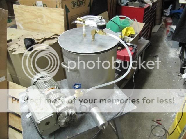
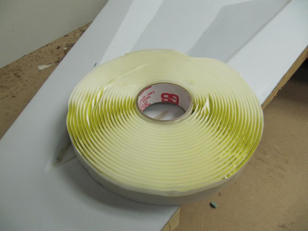
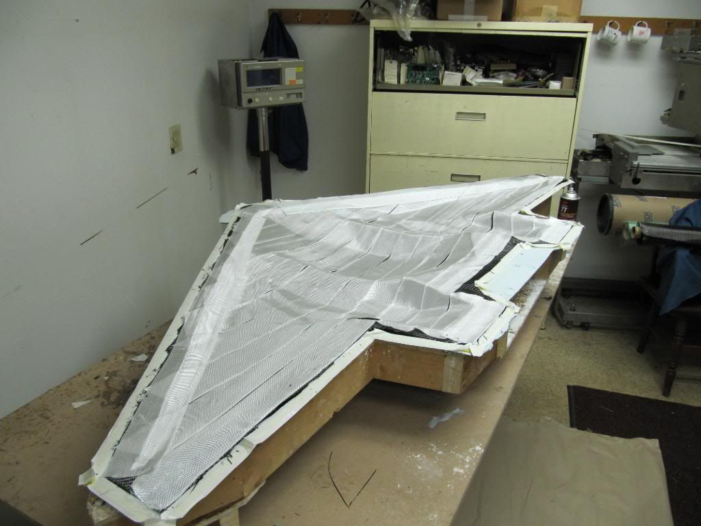
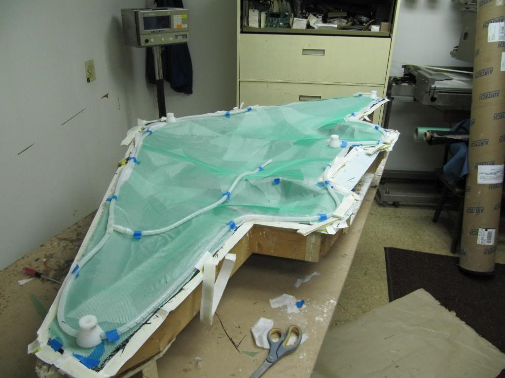
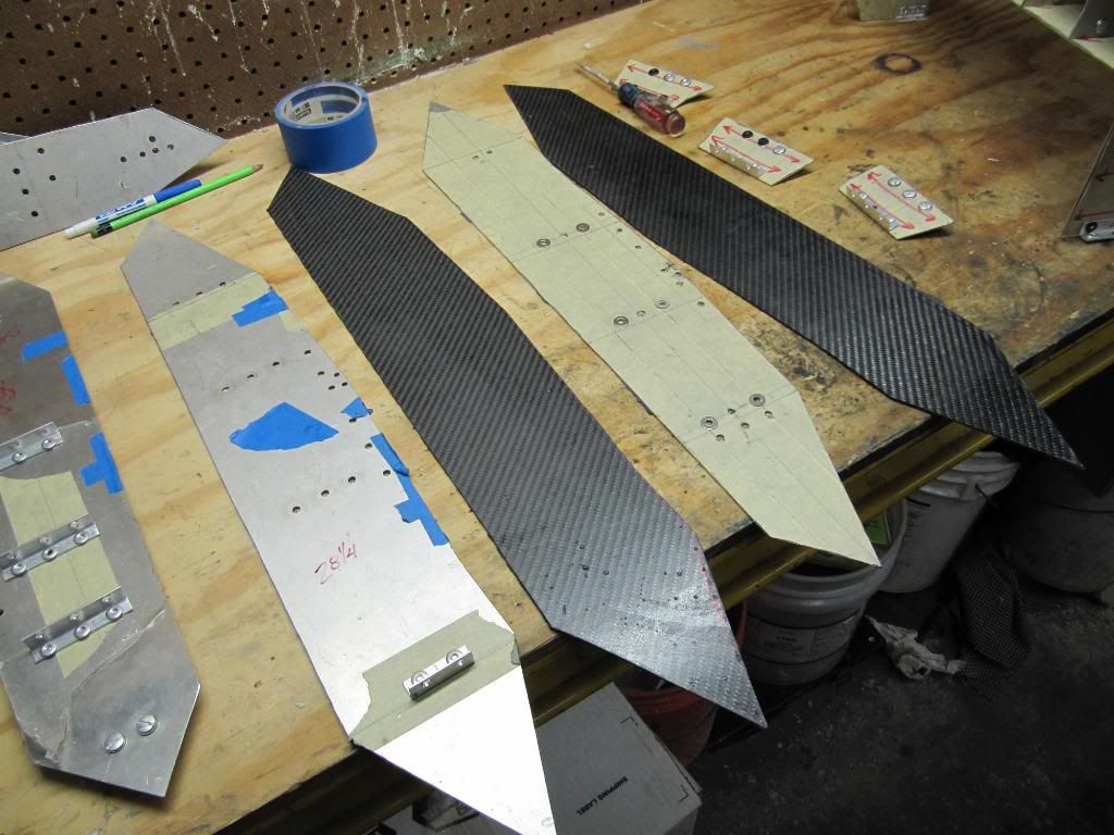
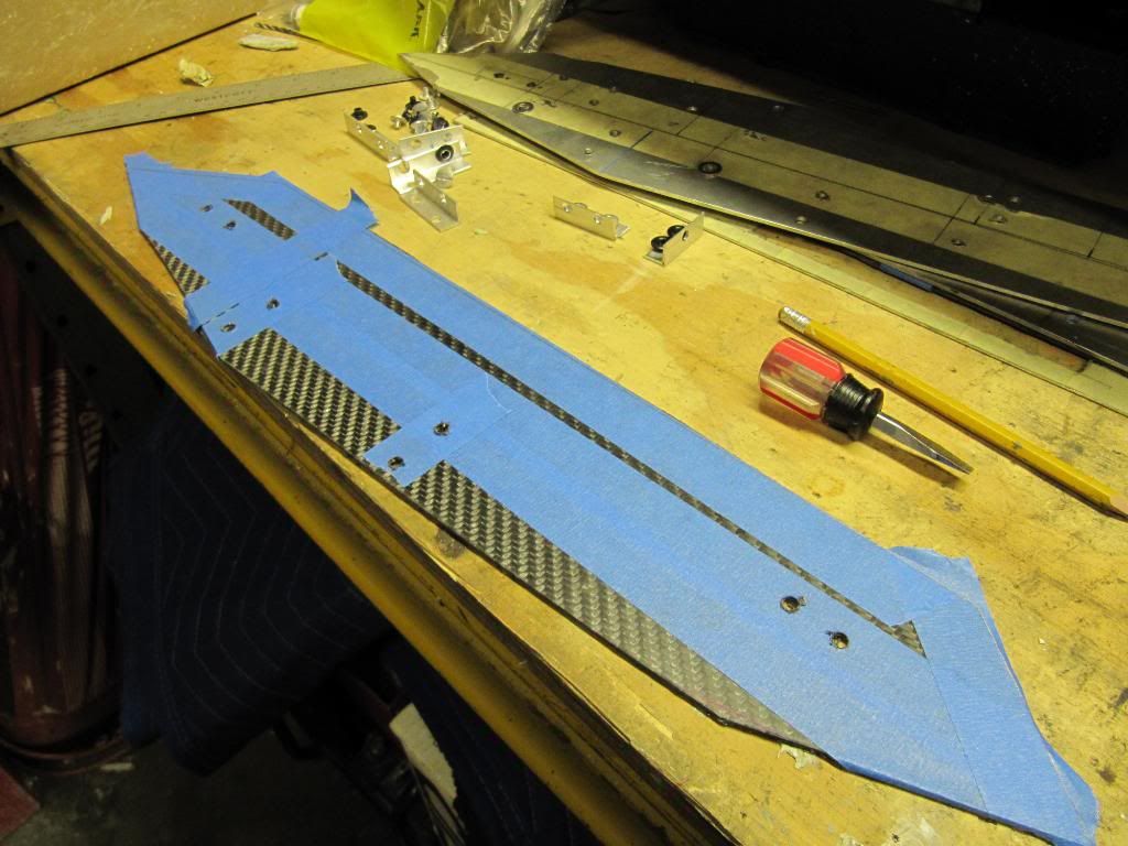
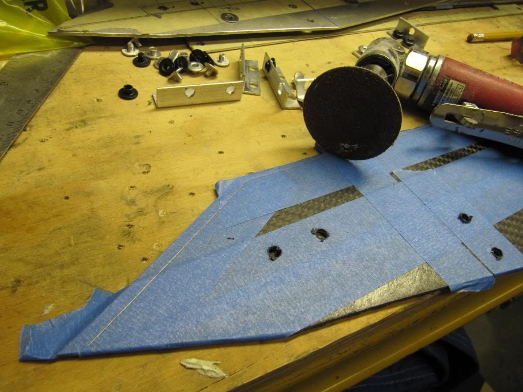
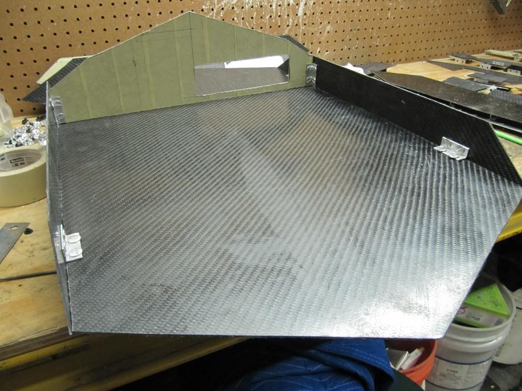
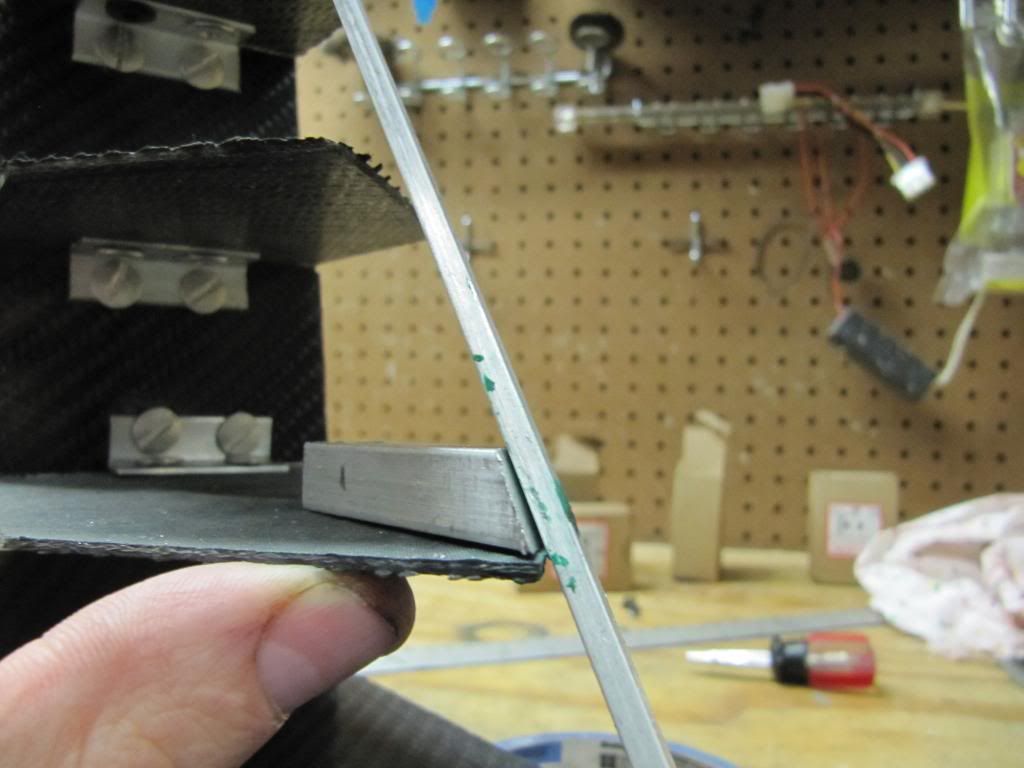
Happy New Year!! 2012 is going to be a great year in modding. I hope you all didn't think this build was dead:nono: Holidays in the US are tough to get materials out of suppliers, so the waiting game takes hold. In the meantime, instead of buying a pressure pot/resin trap, I decided to build one.

I went to Home Depot and bought some 4 inch PVC pipe with two ends that screwed in. The one ended I cemented in place and I cement the rest of the pipe sections together to leave what you see below.

IMG_3559.jpg


I than got lucky cause I needed a gasket to make a secure seal when the top was screwed down. I venture down the faucet accessories aisle and found a 4 inch gasket that goes underneath your faucet. :clap:

IMG_3560.jpg


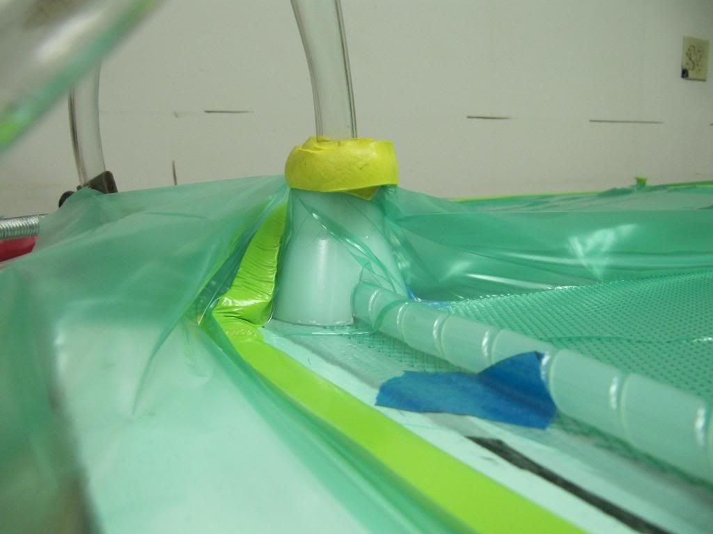
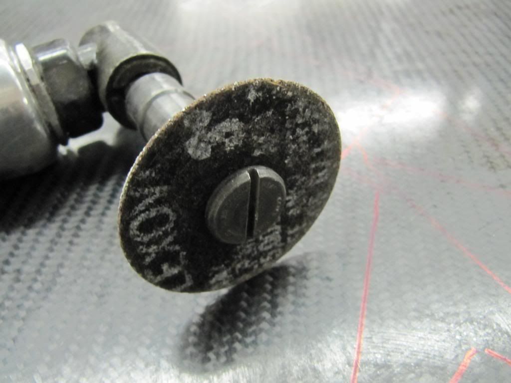
I drilled, tap, telfon taped, screwed in some barb fitting 1/2" into the top cover.

IMG_3562.jpg


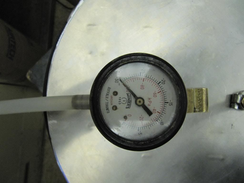
I have already tested my pressure pot. I got get some pictures up. That will be later today.
 
You know, I was suppose to upload some more pics of the pressure pot and I didnt get around to it, cause I started working on the upholstery for SR-X.

So...before I order this carbon fiber and begin the Vacuum Resin Infusion, I have to make a template for covers that will be made out of carbon fiber. Last thing I want to do is be guessing on how to properly cut the carbon fiber only to screw up and have to throw away serious cash. The solution to this is quite simple, get cheap or free cloth and make a template out of that first.

As you will see below, my covers are not flat and are highly geometrical, so the way the carbon fiber is going to lay in there is tricky. I was wondering how to keep the fabric in the mold down and flat, than, I came up with using salt which we have a whole 55 gallon bucket of to do the trick.

IMG_3563.jpg


This is my first try by the way, so I laid out the fabric and start placing in the salt. The corners are the trickest places to get the fabric to cooperate.

IMG_3564.jpg


These corners were a devil. What happens is that as you lay in the fabric you are going to have wrinkles on the flange and in the mold side. To get these wrinkles out relief cuts have to be made, you will see in a second, so to make the fabric sit flat against the faces.

IMG_3565.jpg


the whole mold filled with salt. The first go around didnt really pan out, Round Two.

IMG_3566.jpg


Placed a new sheet of fabric across the mold, though, this time I began from the center and work outward. Placing in coffee cups full of salt at a time.

IMG_3567.jpg


Got the middle down and where I want it to be.

IMG_3568.jpg


Than poured along the front of the piece. See how the fabric is flat against the walls. The salt also helped to hold the fabric down, which was a big plus.

IMG_3569.jpg


IMG_3570.jpg


here is a Relief cut. This was wrinkle in the fabric due to the geometry so a cut had to be made. The fabric will overlap each other which is fine. I dont care about the flange, it will get cut-off and thrown away. Resin will still flow fine along these relief cuts.

IMG_3571.jpg


I trimmed the excess fabric around the mold to get my basic template. Job Done. :clap:
Now just fold the fabric up and dump the salt out.

IMG_3572.jpg


This piece is an excess piece that will be made in a flat carbon fiber panel and used to re-fabricate the frame of SR-X in carbon fiber. The tape measure next to it, is set at 8 feet sinse that will be the length of the table. I dont want to have carbon fiber just sitting around and since I will have alot extra why not make the entire frame out of carbon fiber. My pocket is feeling some pain right now........

IMG_3573.jpg


Lastly here is my template for the bottom cover. It is 86 inches long by 36 inches wide. There will be 3 layers of carbon fiber with titanium foil in the middle of one of the layers. If you are wondering, that is alot of carbon fiber too.
 
Wow, I truly admire your skills and devotion to this. What exactly is the pressure pot for? I skimmed thru the thread but didn't notice a specific description of it's use/purpose.
 
Wow, I truly admire your skills and devotion to this. What exactly is the pressure pot for? I skimmed thru the thread but didn't notice a specific description of it's use/purpose.

Thank you! The pressure pot is for monitoring pressure before and during the infusion of the resin. It also is a resin trap. To get all the air bubbles out, excess resin will be pulled thru to this pot. The pot makes sure that no resin reaches the vacuum pump.Tune in if you really want to see how to make carbon fiber part.:D

intense build

Thanks!
 
Thank you! The pressure pot is for monitoring pressure before and during the infusion of the resin. It also is a resin trap. To get all the air bubbles out, excess resin will be pulled thru to this pot. The pot makes sure that no resin reaches the vacuum pump.Tune in if you really want to see how to make carbon fiber part.:D

Sounds interesting. I will definitely be watching the rest of this! Cool stuff for sure! :)
 
Hello. I looked back at my log and saw I did not have a whole lot of mold pictures, so I took some this morning for the community.

I took the pictures from several angles and different lighting situations. I dont have the best environment for pictures nor is my camera a DSLR. I try to make due with the best I got. Hope you all like them, I am trying to get better at photography.:dremel: Tomorrow is going to be an exciting day.

IMG_3574.jpg


IMG_3575.jpg


IMG_3576.jpg


IMG_3577.jpg


IMG_3578.jpg


IMG_3579.jpg


IMG_3580.jpg


IMG_3581.jpg


IMG_3582.jpg
 
niiiiiiiiiiiiiiiiiiiiiiiiiiiiiiiiiiiiiiiiiiiice
 
Hello. It has been a long moment since my last Log. I have been busy working on the molds getting them prepared for the Vacuum Resin Infusion process. I was also waiting for materials to come into Ohio where I am located by shipment. Finally got the materials and the molds the way that I wanted them.

Vacuum Resin Infusion Tutorial

There are two methods to form carbon fiber from a fabric to a hard composite.

1. Vacuum Bagging: This process starts out with a mold. The CF is laid down onto the mold and covered with Resin by a brush or a roller. A Vacuum Bag is applied over the mold and a vacuum is induced thru a connection on the vacuum bag. During this process excess resin is pulled out and the feed line is clamped off after a certain point of time to let the Carbon Fiber to cure and dry.

This process is the traditional method used by most people. Due to its simplicity and more fool-proof method. The BIG down side is that the properties of carbon fiber is lost using this process. The excellent strength to weight ratio with be diminished. Resin will not be applied at evenly across the fabric either.

2. Vacuum Resin Infusion: This process starts out with a negative mold. Carbon Fiber is laid down into the mold and a Vacuum Bag is applied over the mold. In infusion there is an infeed line for Resin and outlet line that leads to the vacuum pump. They are placed usually on the opposite ends of the mold. A vacuum is induced and the resin infeed line is opened up. Resin with will drawn in by the vacuum and spread over the mold eventually leading its way to the outlet line.

Infusion can lead to completely perfect carbon fiber part. Every void in the carbon fiber fabric is filled with resin. This leads to excellent weight to strength ratio. Infusion is not highly used due to additional cost, complexity, and possibility for errors.

I utilized Vacuum Resin Infusion for SR-X because this process has not been done in the Computer Modding community. I wanted to do something challenging and brand new to community.

[SIZE="4"]Materials [/SIZE]

IMG_3587.jpg

Double Sided Seal Tape

IMG_3588.jpg

Infusion Connector

IMG_3590.jpg


IMG_3591.jpg

Tubing

IMG_3593.jpg

Partall Wax or something similar can be used.

IMG_3596.jpg

Infusion Resin: PTM-W is where i got my infusion resin. Cheapest too!

IMG_3597.jpg

Vacuum Pump

IMG_3599.jpg


IMG_3592.jpg

Misc Stuff

IMG_3600.jpg

Resin Trap

IMG_3607.jpg


IMG_3609.jpg

Carbon Fiber 3oz 2x2 twill

IMG_3641.jpg

Green Flow Media

IMG_3657.jpg

Scale

The last two items are vacuum bagging material and peel ply. You will see those during the process.

Infusion Set-Up and Process

IMG_3712.jpg


You always wax or apply a release agent before you start your setup. I applied 8 coats of wax across the entire mold. I start by applying the double-sided seal tape.

IMG_3714.jpg


This roll was 25 ft and I used up most of the roll. On corners I applied extra seal tape due to the pressure once the vacuum is applied. This helps so the seal tape doesnt come up.

IMG_3715.jpg


This is an optional item. Due to the complex geometrical shape I used 3M Super 77 spray adhesive to keep the fabric laid down properly in the mold. You can get bridging which is when the carbon fiber is not sitting flat or properly into the corners of the mold, thereby, letting Resin pool under that spot.

IMG_3716.jpg


IMG_3717.jpg


First Layer

IMG_3719.jpg


IMG_3722.jpg


Second Layer

I took the Carbon Fiber and rolled it out across the mold. As I was rolling it out I was laying the carbon fiber into the mold. After reaching the other end of the mold I went around the mold and cut the excess carbon fiber off.

IMG_3723.jpg


The third layer is fiberglass fabric. I was going to use titanium foil here, though, due to cost and availability I had to abandon that idea. I used fiberglass strip material because it would let me lay down the fiberglass better in the mold.

IMG_3724.jpg


IMG_3725.jpg


IMG_3726.jpg


Fiberglass layer complete.

IMG_3727.jpg


IMG_3729.jpg


Fourth Layer.

IMG_3731.jpg


After the final layer, I applied Peel-Ply. Peel Ply is usually a white nylon sheet material. Peel Ply is used in the process for after curing it lets you peel off the green flow media and tubing along with excess resin that can build up. I suggest that peel-ply shouldn't be applied in one continuous layer with a mold that is highly geometrical. Instead cut the peel ply into pieces and lay those pieces in the mold. This will help prevent Bridging from happening.

IMG_3732.jpg


Green Flow media is next. Flow media is used to help distribute the resin properly across the mold. While you don't have to have one continuous layer I chose do so for the purpose of making sure the resin got to all parts of the mold. Some people only use flow media around the inlet and outlet in their infusion process.

IMG_3735.jpg


IMG_3736.jpg


IMG_3737.jpg


IMG_3738.jpg


After the green flow media, the Resin Infusion connectors and Spiral Wrap were laid down. Than the Vacuum Bag was than applied. The spiral wrap can be taped down onto the green flow media to keep it in place. The Vacuum Bag is always bigger than your mold/part by a sizeable amount. Pleats are added to help the Vacuum Bag dip into the mold and get into the corners. Slices are made into the bag over the connectors and the tubing is inserted and clamped off on the infeed ends.

Next up Infusion.
 
With the Vacuum Pump hooked up and a vacuum is pulled on the mold, I went around and checked for leaks around the seal tape. Pushing down pretty hard and working any leaks out of the seal tape is must. You cant actually hear the leaks, so just push down till you hear the sound stop.

IMG_3659-1.jpg


IMG_3660-1.jpg


The resin and hardener are weighed out. The mix ratio was 100-22. I mixed thoroughly and let the resin set for about 10 minutes to let it de-gas and so the air bubbles wouldn't travel in the mold.

IMG_3661.jpg


IMG_3662.jpg


I pulled a vac around 30hg and the temperature was around 80F in the room I was working in.

IMG_3664.jpg


IMG_3665.jpg


Here is the infusion taking place. These pictures are from an earlier process that failed.

IMG_3739.jpg


IMG_3740.jpg


I clamped off the infeed lines and left the vacuum pump running for 24 hours till the carbon fiber was done curing. Which is highly recommended when doing infusion. Also I kept the room between 70-80F so the resin would properly cure.

De-Molding

This is the fun part. With the carbon fiber now cured. I turned off the vacuum pump and started tearing away at the vac bag and underlying layers.

IMG_3741.jpg


IMG_3742.jpg


IMG_3743.jpg


IMG_3744.jpg


IMG_3745.jpg


IMG_3746.jpg


The process is real simple. Just rip of the vacuum bag and seal tape. Than find where you can peel the peel-ply and start pulling real hard and the peel-ply with come off the back of the carbon fiber part. Once this is all done just pop the carbon fiber part out of the mold.

Final Part: Top Cover

IMG_3747.jpg


IMG_3748.jpg


IMG_3749.jpg


IMG_3751.jpg
 
Hello. My thanks once again goes out to the modding community in the support for this build. Update time.......

I had to re-figure a Resin Trap for my infusion setup. The PVC ones that I was building were getting ravaged due to the crystallization process by the infusion resin. The resin heats up to almost 200F when it is setting up to cure. This is actually the curing process itself, though, it doesnt stay this temperature the whole 24 hours. The PVC tubing was just melting and buckling under the heat. So....time for Aluminium!!:clap:

IMG_3757.jpg


Here is the Alum Tank. I salvaged this out of the scrap bin. It is used actually for marinating food in. It will due for me. Plus I wont have to worry about over filling the trap with resin.

IMG_3758.jpg


IMG_3759.jpg


I had some .090 6061 Alum laying around that was left over from the Aelro build. I cut out this round piece to be used as the cover. Drilled some holes and taped them. Than I had some 90 degree stock layin around and had it welded on the backside for support.

IMG_3760.jpg


This is weatherstrip for a garage doors that I bought at Home Depot, it works as a seal!!

IMG_3761.jpg


IMG_3762.jpg


Lastly, I got in my 8 yards of Carbon Fiber to finish the bottom piece and rest of the frame. There is another story behind this, that I will share in the next update!
 
Hello! There is a back story here that I must tell. One of FAILURE!! Resin Infusion is not an easy process or for the light-hearted nor does its mistakes come cheap. Before I infused the top cover as recently logged, my first try was infusing the bottom mold. After weeks of preparation and thought, I went thru the set-up of the mold to infuse it. A

After all I studied and consulted about, I thought my flow layout was good and that the Carbon Fiber was making contact all the way around the mold. It turns out that the CF was bridging in corners and that the flow layout would not reach the very corners.

Which resulted in a FAILED infusion process.

IMG_3686.jpg


If you look closely you will see all sorts of lumps and unevenness. As the CF was infusing the resin flow would not reach the corners resulting in fabric that was not impregnated. :wallbash::wallbash: There was nothing that I could do, infusion once started cannot be corrected if there is an error.

After the CF cured I pulled it out of the mold and found pools of resin in the mold from where the CF was bridging, which was causing the resin to pool due to no-contact there with the mold in the spot.

IMG_3687.jpg


So I moved on to the Top Mold and was left chiseling and re-sanding the entire bottom mold. :dremel:

In the end, the first infusion process ended up costing me ~$300.00 in material. I never figured out the exact cost.

Well time to get to the bottom mold again and the infusing the lower cover.

Infusion Lower Cover: Part 1

First thing I did was Wax the entire mold 9 times with Partall Wax #2. This acts as the release agent in the mold.

Secondly, as you see below, after waxing, I applied the double-sided yellow tape that seals the mold for infusion. It seals the nylon vac bag to the mold.

IMG_3799.jpg


IMG_3800.jpg


IMG_3801.jpg


Once again, I went around the entire mold and reinforced the corners with extra pieces. You peel the top off when you go to apply the vac. bag.

IMG_3802.jpg


IMG_3803.jpg


First layer of the Carbon Fiber. Before I laid this layer in I did spray over the mold with 3M Super 77 spray adhesive. I was about 3 feet away from the mold when I did the spraying, so to let the mist float down onto the mold. To much spray and the CF wont release.

IMG_3804.jpg


First layer cut

IMG_3805.jpg


Second layer after cutting

IMG_3806.jpg


The third layer again is strips of fiberglass cloth. I found strips to be easier to apply than one whole layer due to the complex geometry. Supposedly, fiberglass cant be laid down as tight as CF can.

IMG_3807.jpg


Fiberglass layer complete

IMG_3808.jpg


Flow lines with peel-ply and green flow media laid down. Now to just put in pleats along with the vac. bag and begin the infusion.

That is tomorrow. Stay Tuned.
 
Hello. It has been 24 hours and the lower cover has finally cured now it is time to Rip it out of the mold. Lets Begin!:thumb:

Here is the first video of the infusion, I will be uploading a second video! Thanks Mosquito!

http://youtu.be/D-w0U74oma4

First thing is to shut the pump off! Than begin tearing away the all the top layers


IMG_3824.jpg


Take out the infeed hoses

IMG_3825.jpg


Grab at the nylon bag and just tear away.

IMG_3826.jpg


IMG_3827.jpg


Keep tearing away until the vac bag is completely off. The Yellow seal tape also has to come off as well before the part can be demolded.

IMG_3828.jpg


IMG_3829.jpg


IMG_3830.jpg


Next is Rip off the peel ply layer. The peel ply will also rip off the green flow media. You can use a razor blade or knife and make smaller cut lines to rip the peel ply off in sections.

Lower Cover

IMG_3831.jpg


IMG_3832.jpg


IMG_3833.jpg


IMG_3834.jpg


IMG_3835.jpg


IMG_3836.jpg
 
great job, beautiful.. Amazing to see the beginning product in transformation =)

Thank you!

Update Time

I did film a second infusion video and I uploaded it today.

[YOUTUBE]T0I9_HBEA8k[/YOUTUBE]

The video demonstrates the complexity with doing resin infusion and various infeed lines that had to be used to complete the infusion itself.

Moving on.........

I have one more infusion to do for the frame pieces. I dont know how much area/material I need to make to accommodate all the frame pieces. I'm too lazy to figure it out in SolidWorks. So I took the internal frame apart and traced the pieces onto a piece of cardboard that would be the size of carbon fiber fabric that I would infuse. Neat Trick, I think!

IMG_3844.jpg


IMG_3845.jpg


IMG_3843.jpg


All the pieces were traced twice, except the motherboard frame. Once the third infusion is done, I will get to work on cutting out the internal frame pieces and fabricating the bracketing to hold the covers onto the frame.:dremel:
 
Not sure if there's already been a Mother of God meme in this thread but it deserves one. Keep up the good work
 
Hello. When I first started the build I originally intended to have an Aluminium frame structure for the interior. That changed when I found out that I had enough left over material to make the entire frame out of carbon fiber. Plus I also said what the heck why not. Let SR-X be an all carbon fiber build.

Today, I finally started what I thought was going to be my last infusion. Here is how the process started out once again.

IMG_3846.jpg


Flat whiteboard from Home Depot. Wax 7 times, thick coats. Applied the yellow seal tape. Than sprayed with 3M Super 77.

IMG_3847.jpg


The first layer of carbon fiber

IMG_3848.jpg


two more layers of carbon fiber later and first layer of fiberglass.

IMG_3849.jpg


I cross-hatched the fiberglass for additional strength and rigidity.

IMG_3850.jpg


the 6th layer. this would be the fourth layer of carbon fiber

IMG_3851.jpg


Applied my tubing and vac. bag. I kept the flow pattern simple. One infeed inlet and one outfeed outlet with spiral wrap to help the distribute the flow.

IMG_3852.jpg


IMG_3856.jpg


Poured the Resin and just waiting for hardener.

IMG_3855.jpg


Got a good -30bar on the infusion piece

IMG_3859.jpg


Started my infusion and it stopped two-thirds of the way. Ugh! It is a bad thing and a good thing.

IMG_3858.jpg


IMG_3861.jpg


Bad thing cause if it would have made it to 50" I would have been happy. Now I have to order more resin and do another infusion. Good Thing, because the only material I really lost was resin in the end. The material that didn't get impregnated can still be used. Just more and more work. :dremel::wallbash: I still have alot of carbon fiber still left over too.

While we are on the subject of failures and not, here is some more pics of my failed lower cover again.

IMG_3862.jpg


IMG_3863.jpg


I should put "I got Owned" on these pictures, lolz.

I did also shoot some video of this infusion so when I upload it, I will link it.
 
Hello. Time for another weekend update.

During the last 24 hours the carbon fiber piece that was started yesterday has finally cured. Time to de-mold the product.

IMG_3864.jpg


Ripped off the vac bag and starting peeling back the peel ply and such until finally most of it came off.

IMG_3865.jpg


Here is the piece turned over. I cut out the loose fabric on the other end.

IMG_3866.jpg


IMG_3867.jpg


Looks pretty good. I got infusion of flat pieces down real good now. This piece just has to be cleaned and polished up.

IMG_3868.jpg


The section of fabric that did not get impregnated. Oh well.

IMG_3869.jpg


IMG_3870.jpg


The surprise is that I traced all my pieces and I have enough to make the whole frame. I hope you can all see the traced pieces in these photos. So for now there will be no other infusion.

Now I have to get down to cutting out the frame pieces and re-bolting the frame together, than onto bracketing and making the custom res. for SR-X.
 
From the second picture I thought. Airplane! and then have enjoyed the hour long read on your adventure! Very Awesome! Looks like you still have a long road ahead... ;) God Speed!
 
Hello. After some long thought about exactly how to cut the carbon fiber, I decided to stay with my fiber cut-off wheel. I researched for a round saw blade, though, that would shredded the fiber during cutting. I would also rule out the use of hack saw due to the straight cuts and precision that is needed. I practiced with the fiber cut-off disc on failed lower cover it worked the best out of all the options. Also, the use of a jigsaw, once again would shredded the fiber along the cutting line in my opinion.

IMG_3872.jpg


IMG_3873.jpg


Air-Tool with the fiber cutting disc. I operate mine at 120psi to get good constant cutting speed.

The lower the psi the more the disc tends to jump and not cut.

IMG_3877.jpg


The disc does an pretty good job at cutting a good line. No real presence of shred marks. Also can see that the carbon fiber is alittle thicker here than the aluminium piece.

IMG_3874.jpg


IMG_3878.jpg


IMG_3879.jpg


Did some tracing and cutting here. Here are some of the pieces that I cut out. What is interesting is that .040 Alum and ~.050 carbon fiber have no weight difference. The strength and rigidity on the other hand between the two is great! I can start to bend the Alum piece in this picture in certain positions, though, in those same positions I CANNOT bend the carbon fiber.

IMG_3876.jpg


Lastly, this piece which is the motherboard frame is actually what I cut out first today. The Alum piece weighs in at 3.7lbs. The carbon fiber piece wieghs in at 1.7lbs. That is a 2 lb difference. Plus the carbon fiber is just as rigid and strong.

More cutting tomorrow....
 
This is the craziest and greatest computer case I've ever seen... So much work, such a killer look, such a detailed write up... whao !!
 
I have followed this one since the beginning, and it is shaping up nicely! Way to stay the course, and the full carbon fiber treatment is awesome!
 
This is the craziest and greatest computer case I've ever seen... So much work, such a killer look, such a detailed write up... whao !!

Thanks, I'm working hard!

I have followed this one since the beginning, and it is shaping up nicely! Way to stay the course, and the full carbon fiber treatment is awesome!

No other case really out there like it, Thanks for the support

Looks great! Subbed:)

Thanks

this is unreal, congratulations... inspirational

Trying to raise awareness for carbon fiber. Thanks for the support
 
I've followed this mod on and off for a while and I think its finally time to add my $0.02.. this thing is incredible. The design, the attention to detail, the incorporation of all these techniques; its all extremely impressive. I look forward to the finished product!
 
Hello. Time for a weekend update part 1.

I finished cutting out all the pieces for the frame this past week. Now I have begun to re-drill all the holes and re-assemble the frame.

The frame re-build is just like first stage into finishing SR-X. I putting the frame together because all the frames pieces need to be drilled but also test fit. From here, I will probably move either onto the custom Res. that will sit in one of the wing structures or I will......hhhmmm......I'm still plotting it all out. Ah yes, brackets will could be made next to hold the frame structure to the covers. Though, the frame will have to be completely taken back apart maybe dozen more times after this for adjustments and finally polishing and cleaning. Anyways, lets get started:clap:

IMG_3889.jpg


IMG_3890.jpg


I drilled the motherboard tray frame first. Drilling Carbon Fiber is like cutting butter. There is no fighting that can happen on Aluminium thin aluminium sheets. No odor like cutting, though, it is much dirtier than drilling Aluminium.

IMG_3891.jpg


IMG_3892.jpg


I put down blue masking tape and traced than cut, sanded, and drilled. Whatever was needed.

IMG_3896.jpg


Here is a picture to show you what Carbon Fiber looks like after sanding it down with an air-tool.

IMG_3897.jpg


IMG_3898.jpg


Starting to assemble the main center frame piece.

IMG_3900.jpg


Man, computer hardware looks awesome sitting on carbon fiber. :thumb::rock:

IMG_3901.jpg


IMG_3902.jpg


IMG_3903.jpg


More cutting, drilling and assembling.

IMG_3904.jpg


Quick peak of the carbon fiber frame sitting in the lower cover. Looks Awesome!
 
Hello. Been working and forgetting my camera at the shop. Update time

IMG_3906.jpg


Started to put the right side together.

IMG_3907.jpg


IMG_3908.jpg


More tracing, drilling, and cutting to get the proper assembly and fit

IMG_3909.jpg


IMG_3910.jpg


IMG_3912.jpg


On the right side was able to get the frame piece for the foot to install correctly. Now I can go back and install on the left side. In the last pic. I have to make a few adjustments still to the bracket.

IMG_3913.jpg


IMG_3915.jpg


Put this whole side together for mocking up the res. that will have to be built to go into the wing. Some of these aluminium pieces will be taken out. I didnt want to cut CF material only to waste it.

IMG_3916.jpg


This ruler is mimicking as the bracket that will hold the cover on. There will be these aluminium strips with aluminium blocks behind it in certain locations for bolting to the frame. Stay tuned.

IMG_3914.jpg


I wanted to see how counter-sinking the hex head bolt would look like in CF. CF doesnt drill like metal, the speed has to be real slow and gone extremely slow so not to drill to much off. It will work, just will take more time on each drill.
 
I was going to suggest a layer or 2 of clearcoat over the cf pieces..but I'm too late. One of my friends wraps auto interior and exterior pieces in CF so I know the amount of attention to detail this takes. Nice write up.
 
Hello. Time to Log

IMG_3917.jpg


IMG_3918.jpg


Order some 3/8"x 1/8" x 6 ft aluminium strips and 3/8"x3/8" x 6 ft alum. strip block from mcmaster carr to fabricate the bracketing needed for SR-X. I am using 8/32" countersink hex head bolts for fastening, so I don't need the bracketing to be real wide. Also, I am worried about weight, in trying, to keep the weight as low as possible, I went with a tight clearance you could say.

IMG_3919.jpg


The strip will have to be inset into the wing frames so it will rest flush against the cover for fastening. That means I have to notch out an small area so this can happen.

IMG_3921.jpg


IMG_3922.jpg


Did some measuring and finally cutting

IMG_3923.jpg


Got my tape out to help hold in place for now, though you can see that the alum strip piece rest flush against the cover. Now I need to make some alum. bracket pieces so the strip has something to fasten too.

IMG_3924.jpg


My first attempt went not so well! I did some measuring and than some filing and still the angle wasnt coming out right. I tried a couple times at this and said heck with it. Break out the modeling clay so I can figure out the exact angle that i need.

IMG_3927.jpg


So I used the modeling clay to get my angle and from here I just measured how far back the angle went on each side. Than I made my marks on a new piece and used a hack saw to cut it out.

IMG_3928.jpg


IMG_3929.jpg


IMG_3930.jpg


:clap::dremel: Take that AutoCAD! I had to make some minor adjustments with the file, though, so far so good. These brackets that you see here will be welded to the strip piece and bolted to the CF wing frame pieces.

As always stay tuned.
 
Back
Top