Navigation
Install the app
How to install the app on iOS
Follow along with the video below to see how to install our site as a web app on your home screen.
Note: This feature may not be available in some browsers.
More options
You are using an out of date browser. It may not display this or other websites correctly.
You should upgrade or use an alternative browser.
You should upgrade or use an alternative browser.
Project: Server and Gaming Case
- Thread starter Spotswood
- Start date
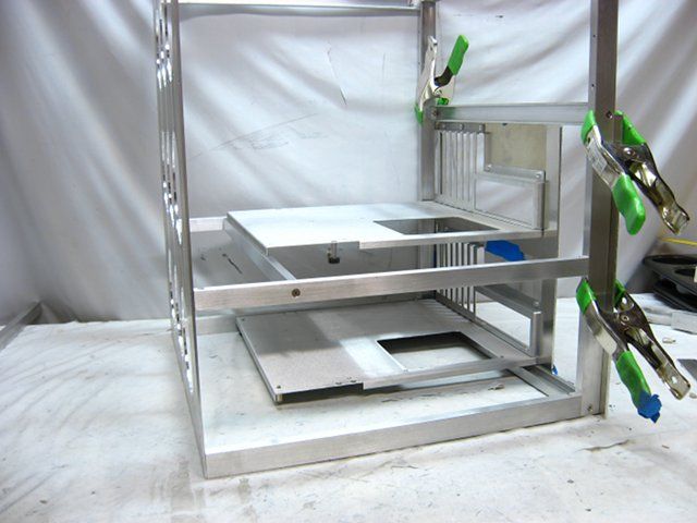
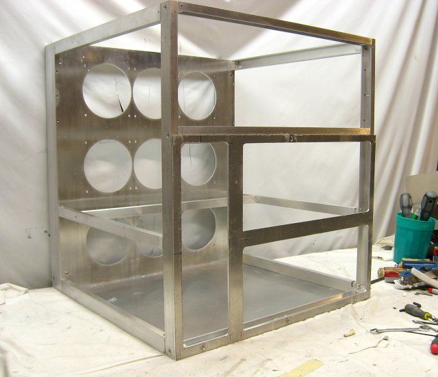
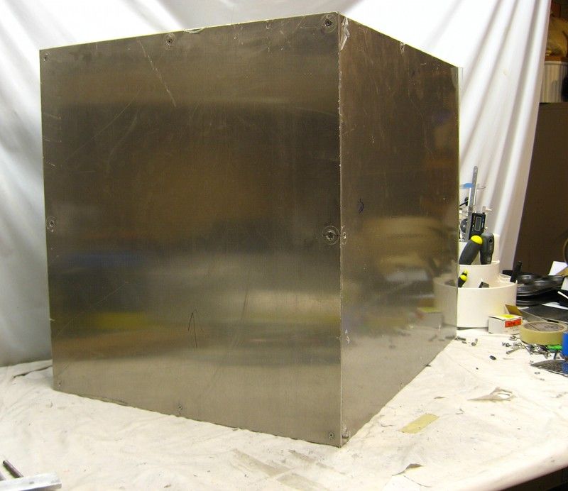
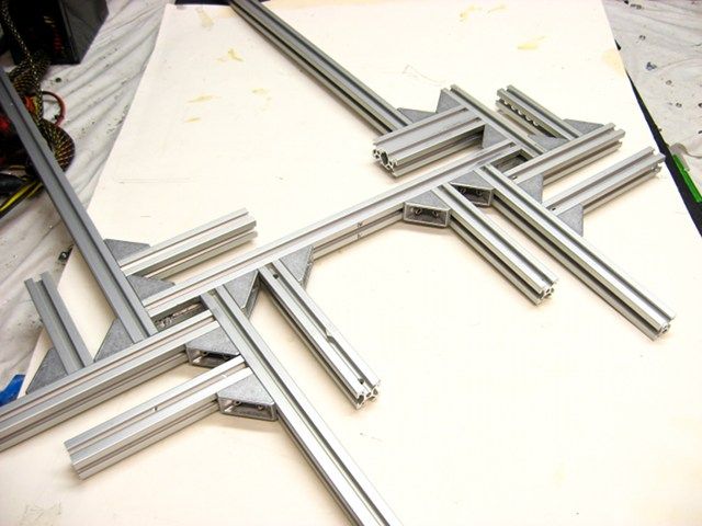
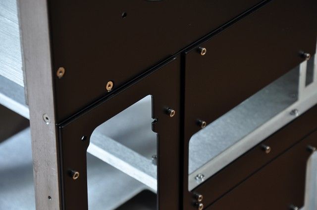
I spent a full day squaring up the case frame, squaring joints, re-aligning joints etc. in preparation of fastening the sheeting.
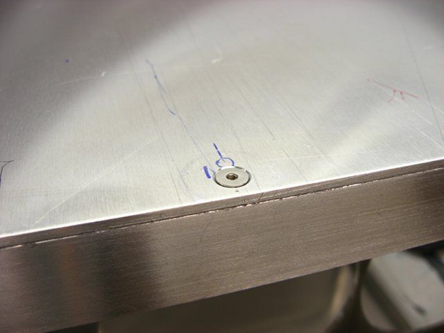
The steps I use to attach a sheet are:
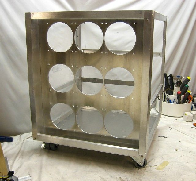
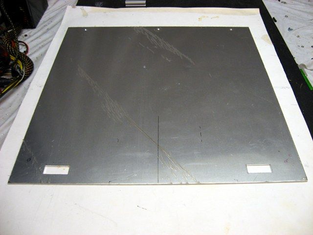
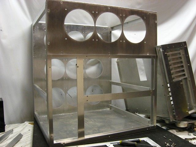
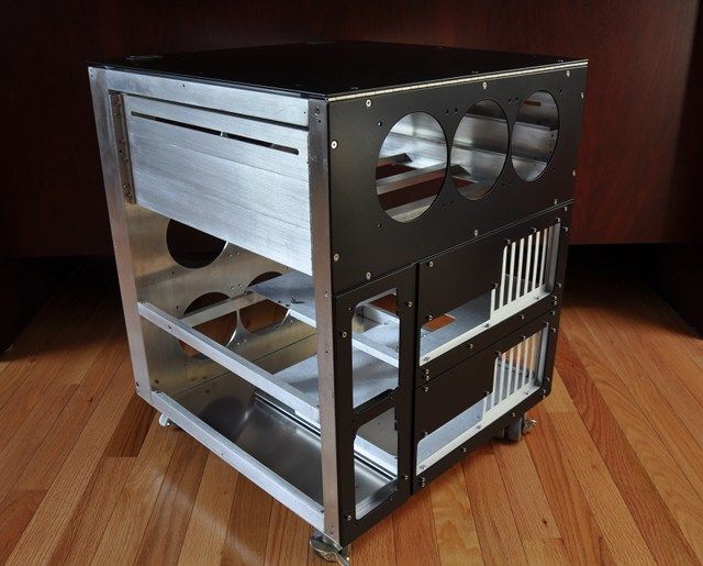
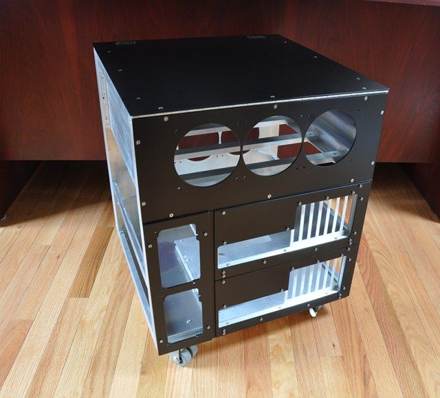
The case with the inner front, bottom and lower back panels attached.
The steps I use to attach a sheet are:
- Drill a hole in the sheet.
- Use the hole in the sheet to guide the drill bit for the hole in the frame.
- Thread the frame hole.
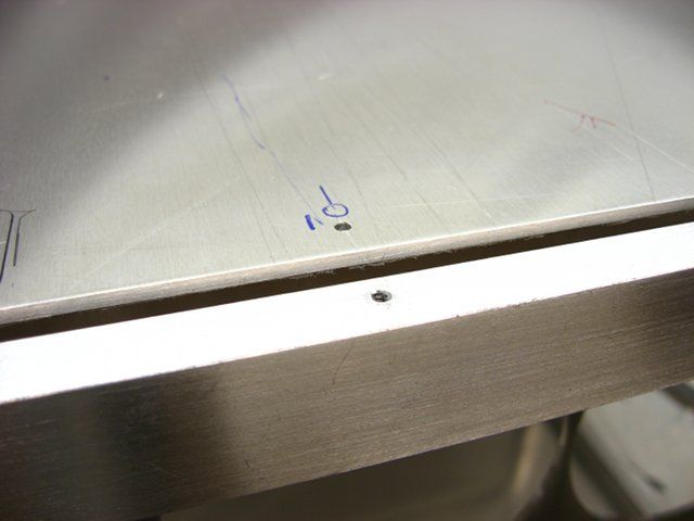
- Countersink the sheet hole.
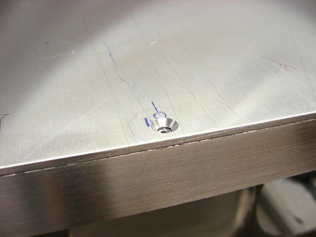
- Admire work.
The case with the inner front, bottom and lower back panels attached.
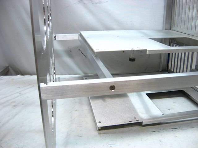
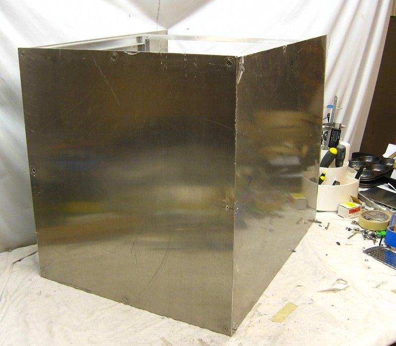
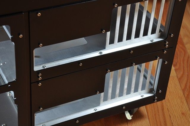
I attached the .1-inch thick side and front panels with 6 stainless steel flat head socket cap screws. The front panel extends past the tops of the side panels by .10-inch in order to hide the top's front edge.
The process to attach the panels is:
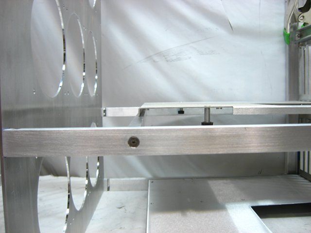
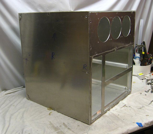
The side panels extend past the top of the frame by the thickness of the hinge. These will later be scribed and cut to length along the back of the case.
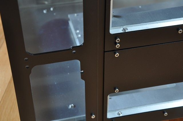
The process to attach the panels is:
- Drill pilot holes along the edges of the panel
- Clamp the panel to frame and use the pilot holes to drill tap holes into the frame
- Remove the panel and tap the frame holes
- Countersink the panel holes
The side panels extend past the top of the frame by the thickness of the hinge. These will later be scribed and cut to length along the back of the case.
omegatotal
Gawd
- Joined
- Mar 15, 2002
- Messages
- 672
looks heavy, will be keeping an eye on this one!
Lord Kanti
Weaksauce
- Joined
- May 21, 2011
- Messages
- 69
What kind of weight are we looking at?
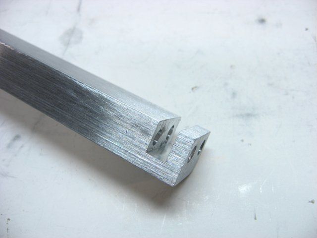
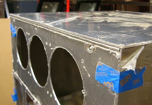
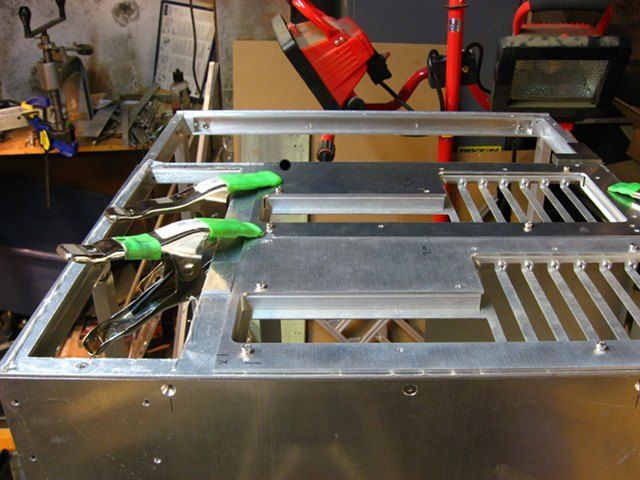
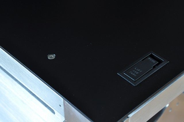
The hinge for the top was cut slightly undersized and centered with a some old business cards used as spacers.
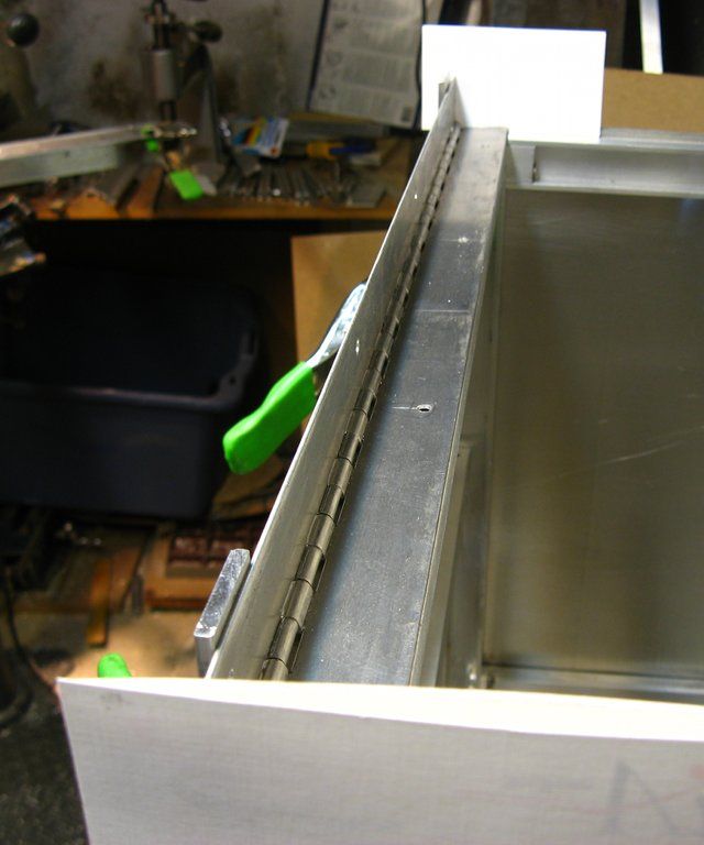
Dimples of aluminum had to be removed from the frame in order to make room for the nuts holding the top sheet to the hinge.
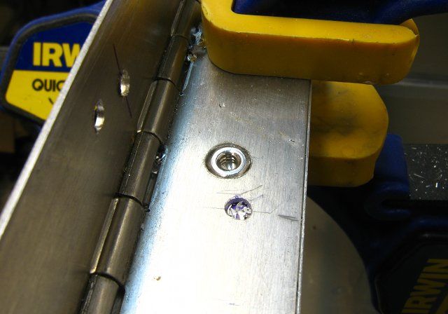
With only a 2.5mm gap between the leaves of the hinge, button head cap screws were used to attach the hinge to the frame.
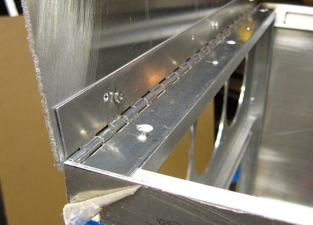
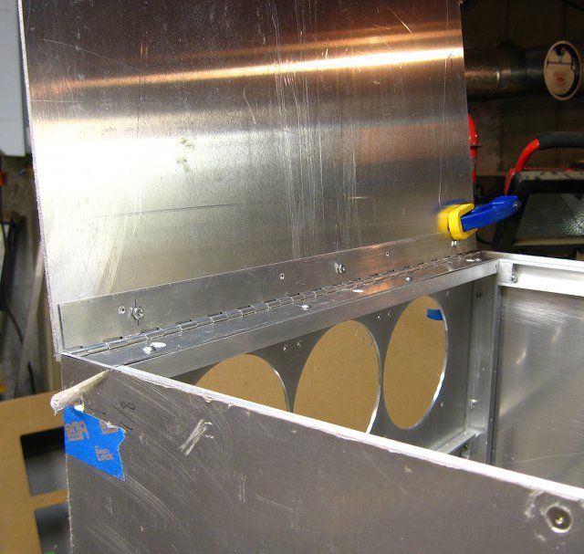
The hinge aligns perfectly with the top sheet, which in turn aligns with the back sheet.
Dimples of aluminum had to be removed from the frame in order to make room for the nuts holding the top sheet to the hinge.
With only a 2.5mm gap between the leaves of the hinge, button head cap screws were used to attach the hinge to the frame.
The hinge aligns perfectly with the top sheet, which in turn aligns with the back sheet.
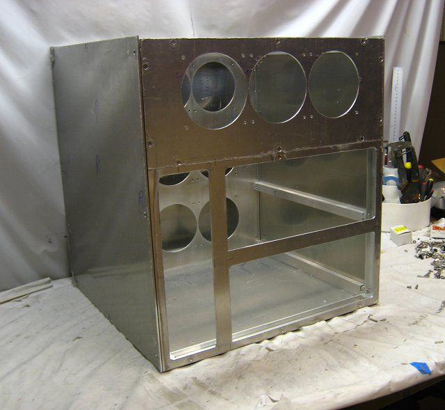
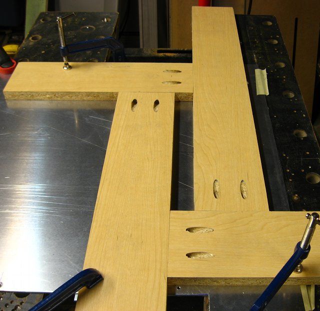
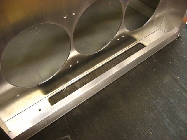
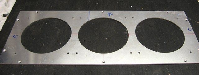
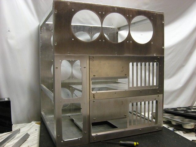
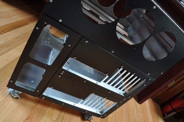
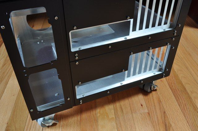
On the bottom of the case, a large slot was cutout which will allow fresh air to enter the front air duct. Following standard operating procedures, a router pattern/template was made at the same size as the desired opening.
The aluminum was removed with my trusty handheld router in two passes, once with a over-hanging pattern bit and another with a flush-cutting pattern bit.
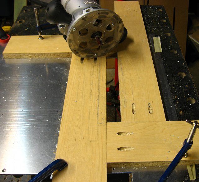
The aluminum was removed with my trusty handheld router in two passes, once with a over-hanging pattern bit and another with a flush-cutting pattern bit.
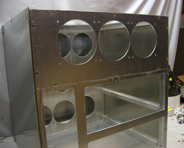
Up next is fabricating a duplicate of the 120mm back fan panel, but for 140mm fans. This time I had Lazerwerx cut me a custom 140mm fan hole router template out of 3/8-inch thick cast acrylic.
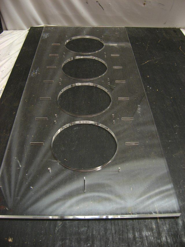
This template is a snap to use: mark center lines and lay the corresponding slits cutout from the template over them.
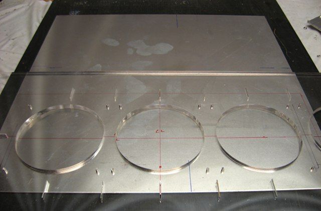
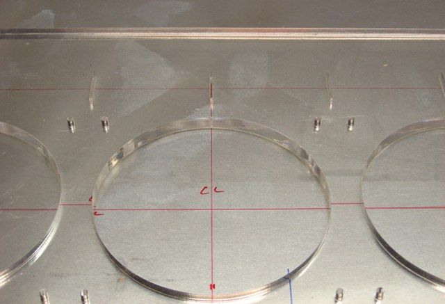
This template is a snap to use: mark center lines and lay the corresponding slits cutout from the template over them.
smiley22432
Limp Gawd
- Joined
- Jun 27, 2012
- Messages
- 161
hopefully aluminum will make that thing light weight!
nlancaster
Gawd
- Joined
- Feb 24, 2005
- Messages
- 700
That much aluminum isnt light. 
lighter then it would be from steel, but still alot of material.
Keep up the interesting work spotswood!
lighter then it would be from steel, but still alot of material.
Keep up the interesting work spotswood!
omegatotal
Gawd
- Joined
- Mar 15, 2002
- Messages
- 672
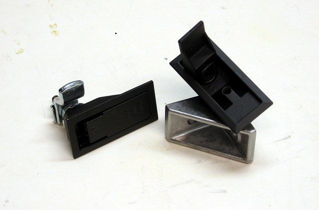
very nice with the T-slot!! also those are very nice latches when they sit flush and properly :-P
jackofalltrades
2[H]4U
- Joined
- Feb 7, 2006
- Messages
- 3,740
Thats alot of work! hope you are getting paid for this.
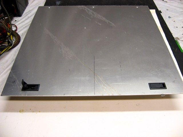
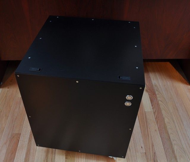
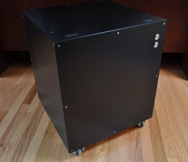
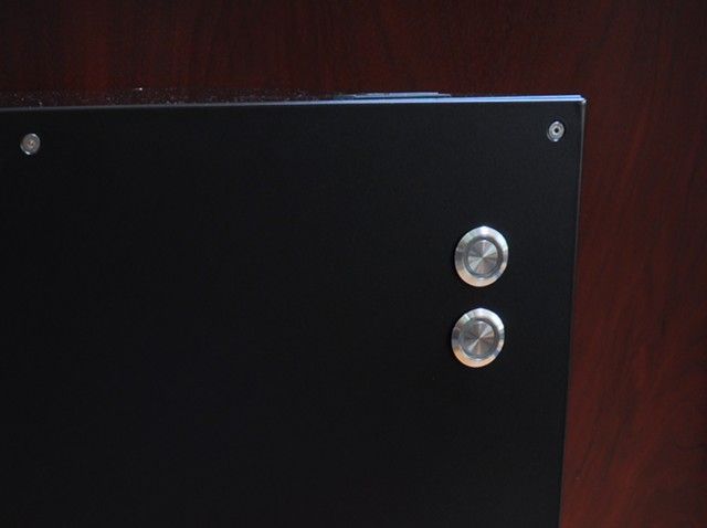
Drilled two 19mm holes for the vandal resistant switches (power and reset/hard drive activity).
Using such a large bit (step drill) is a bit nerve racking for me, but with an extra large work surface and some clamps, I manged to get through it.
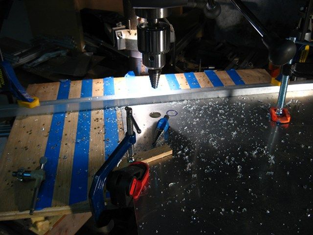
Switches!
Using such a large bit (step drill) is a bit nerve racking for me, but with an extra large work surface and some clamps, I manged to get through it.
Switches!
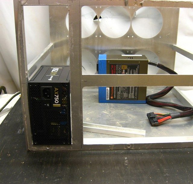
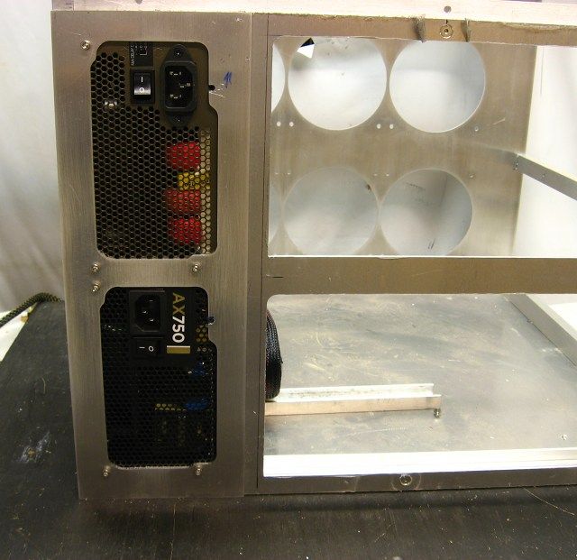
During final assembly (before paint) some rework is inevitable. With this case, early on in the build, it was widened to accommodate the front radiators. But I never went back to see if the PSU mounting bracket worked/looked okay. Plus, I never tested the PSU cutout from the back sheet with the the actual PSUs used for the build. Well, the cutout in the backsheet for the PSUs had to be widened by 3mm in order to clear the fan grill on the PSU cooling fan. And the PSU mounting plate looked to dainty and needed to be widened.
And with the old PSU mounting bracket placed in front of the new one:
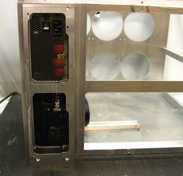
And with the old PSU mounting bracket placed in front of the new one:
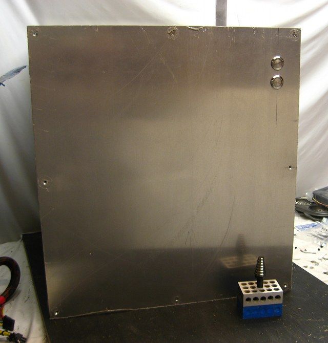
I finished fabricating the back of the case, which consisted of drilling mounting holes through the motherboard trays and PSU mounting plate, through the back sheet and into the case frame. Holes that went into frame were tapped to #6-32 and those in the middle of the sheeting had PEM nuts pressed-in.
robert125381
Limp Gawd
- Joined
- Jul 22, 2012
- Messages
- 143
do you sell or fill out custom orders?
do you sell or fill out custom orders?
I'm real busy atm, but yeah, send me a PM.
gwarren007
Fully [H]
- Joined
- Apr 15, 2006
- Messages
- 21,036
Wow!! Very nice!!!
omegatotal
Gawd
- Joined
- Mar 15, 2002
- Messages
- 672
very nice!
Wahoomcdaniel
Weaksauce
- Joined
- May 2, 2005
- Messages
- 117
Very nice.
I have a question about the top. You have the top hinged with the turn and lock fasteners on the opposite side. There are also six screws on the adjacent two sides, which I would think makes the turn and lock fasteners unneeded. Or did the turn and lock fasteners not provide sufficient holding tension that you though they would?
I have a question about the top. You have the top hinged with the turn and lock fasteners on the opposite side. There are also six screws on the adjacent two sides, which I would think makes the turn and lock fasteners unneeded. Or did the turn and lock fasteners not provide sufficient holding tension that you though they would?