Navigation
Install the app
How to install the app on iOS
Follow along with the video below to see how to install our site as a web app on your home screen.
Note: This feature may not be available in some browsers.
More options
You are using an out of date browser. It may not display this or other websites correctly.
You should upgrade or use an alternative browser.
You should upgrade or use an alternative browser.
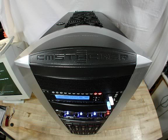
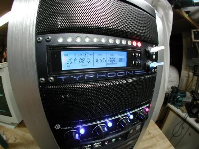
Project: TYPHOON (Stacker+ GTX480) **2010 REBUILD**
- Thread starter JonCl
- Start date
Somebody get it off me!!
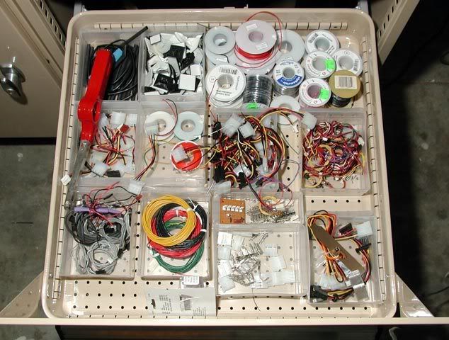
The wife isn't too fond of this drawer LOL...
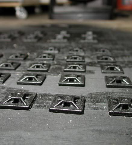
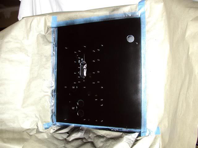
Spray paint "for plastic" works pretty well on white cable tie mounts...
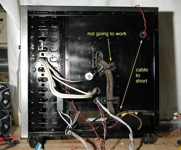
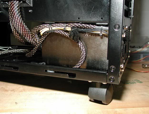
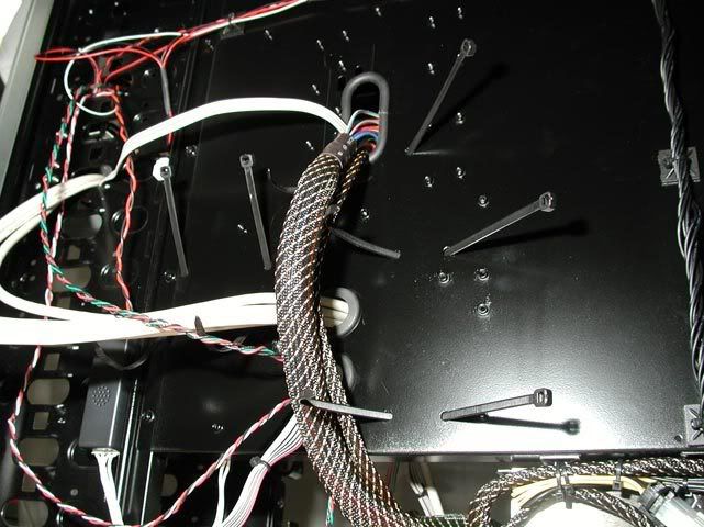
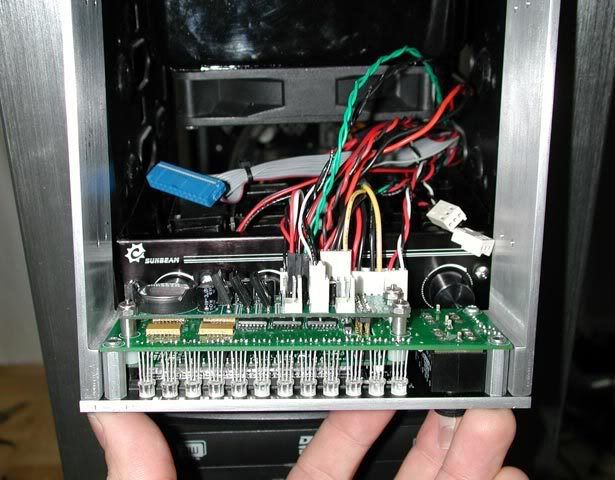
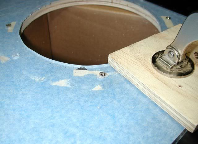
There's not a lot of room on the back of the mobo tray for wires to run between it and the side panel. The anchors around the PSU cable were meant to keep it flat against the tray, but they eventually let loose. So instead, I'll be drilling new holes in the tray to pass the wire tie through that way.
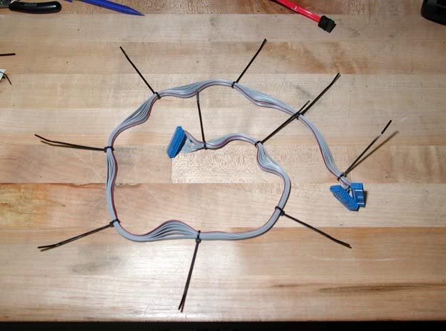
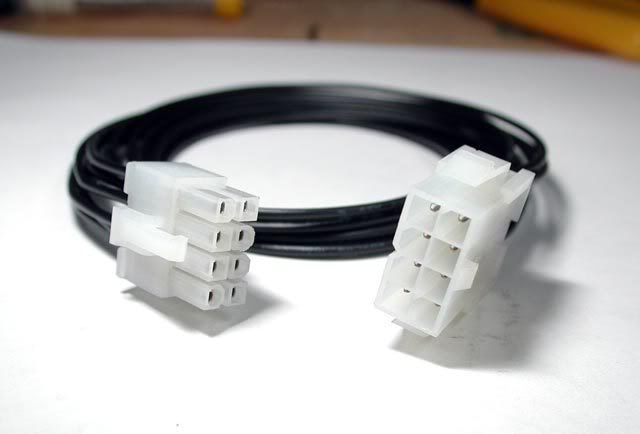
Also, that darned CPU power cable was too short by 1" to reach the mobo plug...
Now the problem was, there wasn't enough room to place an extension over the back of the mobo tray because the plug would be too tall to fit behind the side cover. The only solution I found was to plug a longer extension where there's room at the bottom, and run it up from there...
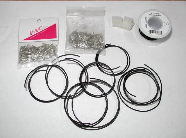
But of course, an extension long enough doesn't exist I guess, so I made my own.
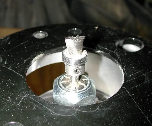
At first, I was just going to cut and splice an existing extension, but then I figured out how to get those pins out of the connector. One side uses a pin extractor...
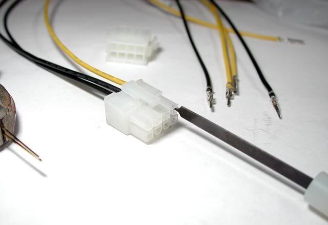
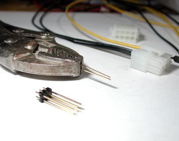
But the pin extractor didn't reach far enough into the other plug, so here's how I did that one...
AND BEGIN!
TIME!
The next update will be more (boring?) wiring and these. What's that wire mount doing on the bottom there? hhmmm...
The wife isn't too fond of this drawer
LOL...
Spray paint "for plastic" works pretty well on white cable tie mounts...
There's not a lot of room on the back of the mobo tray for wires to run between it and the side panel. The anchors around the PSU cable were meant to keep it flat against the tray, but they eventually let loose. So instead, I'll be drilling new holes in the tray to pass the wire tie through that way.
Also, that darned CPU power cable was too short by 1" to reach the mobo plug...
Now the problem was, there wasn't enough room to place an extension over the back of the mobo tray because the plug would be too tall to fit behind the side cover. The only solution I found was to plug a longer extension where there's room at the bottom, and run it up from there...
But of course, an extension long enough doesn't exist I guess, so I made my own.
At first, I was just going to cut and splice an existing extension, but then I figured out how to get those pins out of the connector. One side uses a pin extractor...
But the pin extractor didn't reach far enough into the other plug, so here's how I did that one...
AND BEGIN!
TIME!
The next update will be more (boring?) wiring and these. What's that wire mount doing on the bottom there? hhmmm...
WipeoutFTW
Limp Gawd
- Joined
- Jul 17, 2006
- Messages
- 357
Amazing work. Just read through the worklog today and I cant wait for your next update.
WipeoutFTW, thanks! I'm (finally) rounding the final lap with this project, well at least the building part of it...
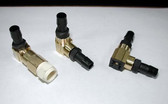
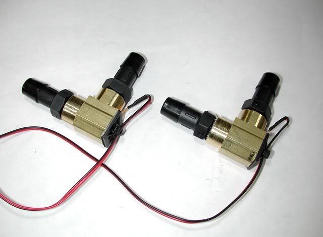
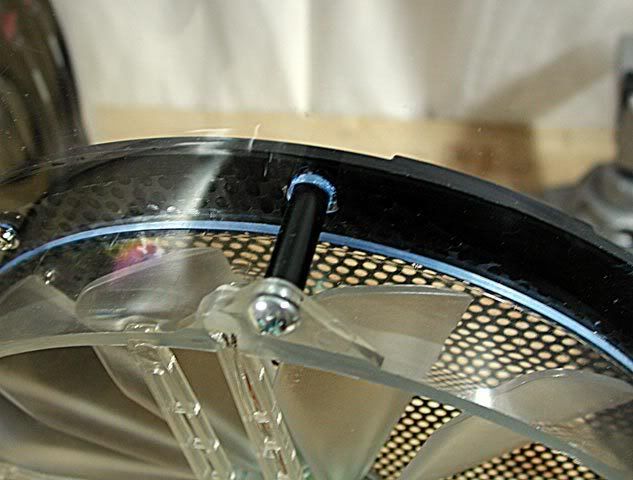
Those brass 90 degrees fittings are going to be temperature sensors...
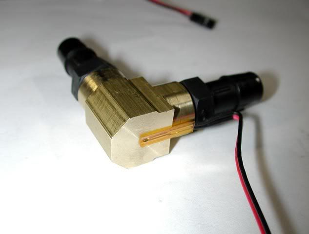
and the stick-on wire mount will serve two purposes: hold the sensor against the brass and hold the wire to the fitting...
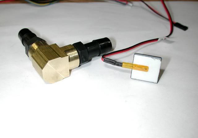
ready to go... well, almost...
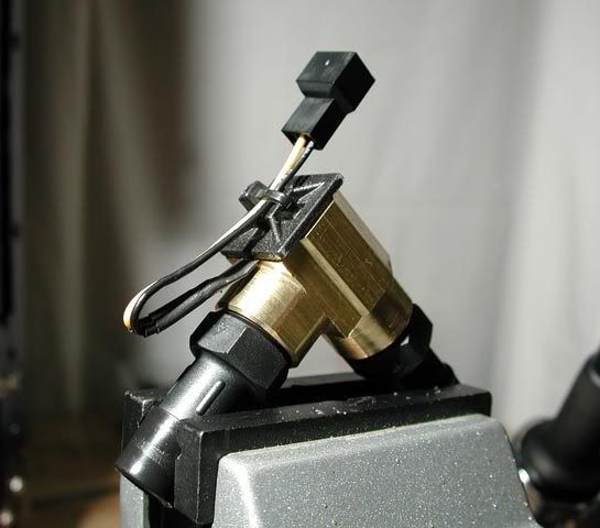
I realized after putting them together that assembling them would be easier if they were modular...
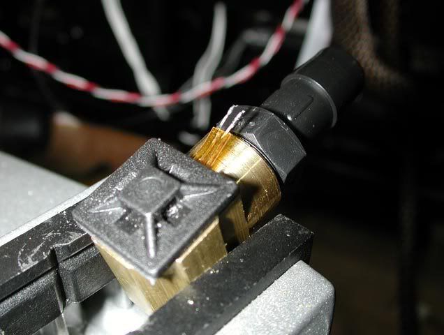
now they're ready...
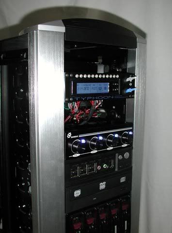
btw, the Logisys panel has three sensor inputs, so I also prepped a third sensor to go on the loop (no picture of it yet). I plan to place the sensors on the loop to make three "sensor zones" between them: radiator, pump, and water blocks. This way, the temperature drop can be determined across each zone.
Back to the case, the paint on the back got screwed up removing those wire mounts (goof off really does melt paint!). So I drilled holes to mount the wires, and prepped the back for a fresh coat...
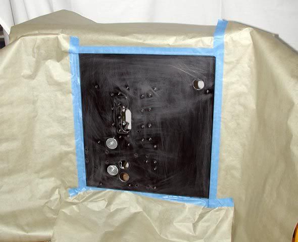
that's better...
After a day, it was dry enough to continue. Here's how the larger cables will mount to the back of the mobo tray...
Here's the work-in-progress...
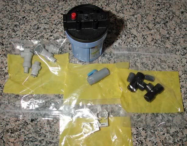
...and finally, just today I received what I think will be the final Mcmaster order for this project. Exactly what the filter and fittings are for, I'm saving until the next update...
Stay tuned, more to come!
Those brass 90 degrees fittings are going to be temperature sensors...
and the stick-on wire mount will serve two purposes: hold the sensor against the brass and hold the wire to the fitting...
ready to go... well, almost...
I realized after putting them together that assembling them would be easier if they were modular...
now they're ready...
btw, the Logisys panel has three sensor inputs, so I also prepped a third sensor to go on the loop (no picture of it yet). I plan to place the sensors on the loop to make three "sensor zones" between them: radiator, pump, and water blocks. This way, the temperature drop can be determined across each zone.
Back to the case, the paint on the back got screwed up removing those wire mounts (goof off really does melt paint!
). So I drilled holes to mount the wires, and prepped the back for a fresh coat...
that's better...
After a day, it was dry enough to continue. Here's how the larger cables will mount to the back of the mobo tray...
Here's the work-in-progress...
...and finally, just today I received what I think will be the final Mcmaster order for this project. Exactly what the filter and fittings are for, I'm saving until the next update...
Stay tuned, more to come!
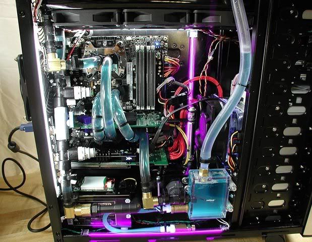
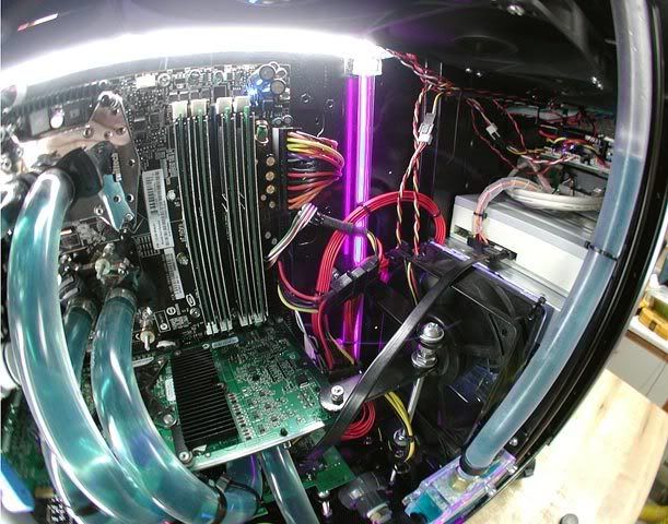
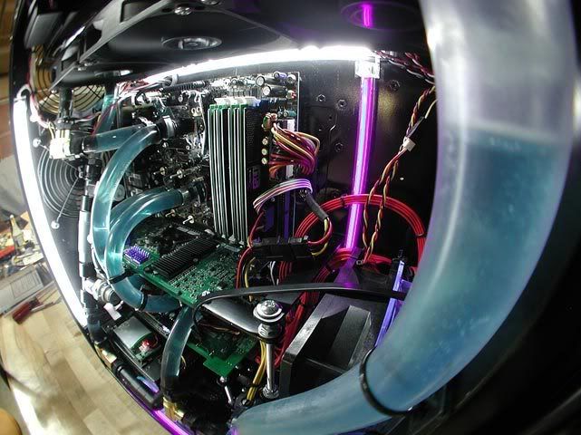
I've taken some bigger strides now, but with one step back (show stopper at the end)...
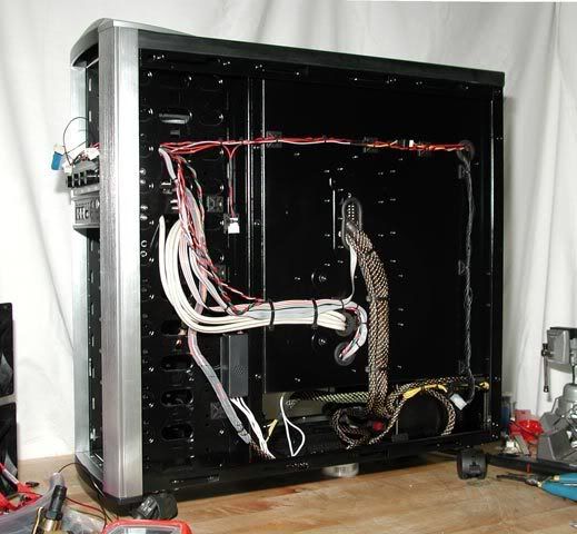
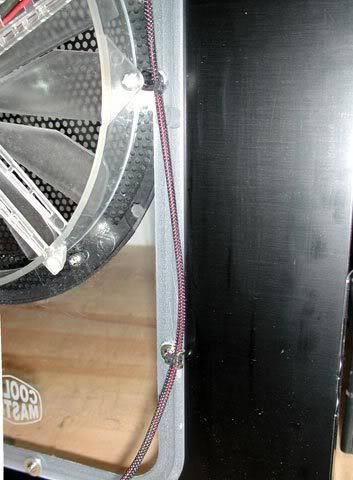
Here's the wiring on the back all ready to be tucked in behind the side panel...
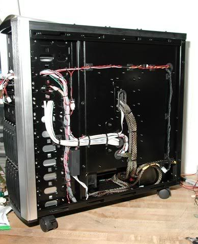
There's only .5" space to fit the cables inside the side panel...
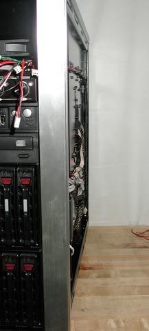
I got it all tucked in except for one or two spots, but they'll squish in so I think the side panel should still go on just fine...
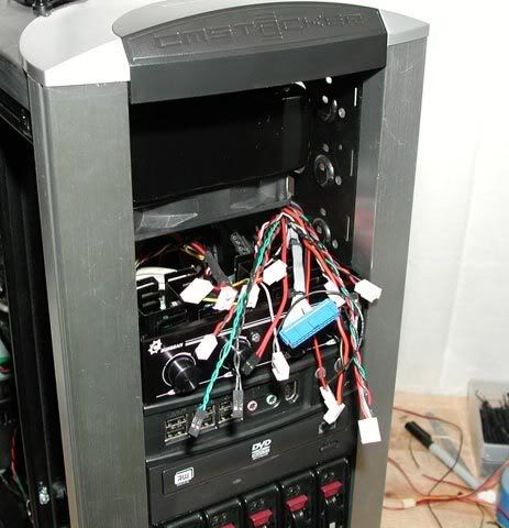
Next, it was time to assemble the front panel...
Here's the system being tested on a spare power supply. Everything is working so far...
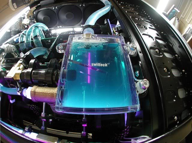
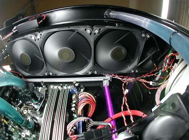
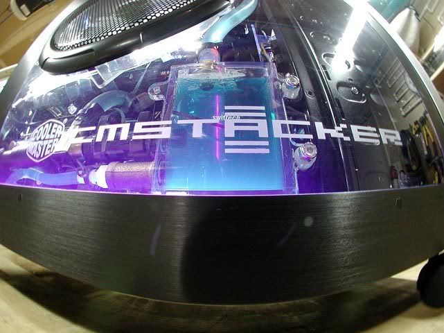
Now, onto hooking up the water loop. First task is to assemble the pump. The plumbing was redesigned to include the temperature sensor...
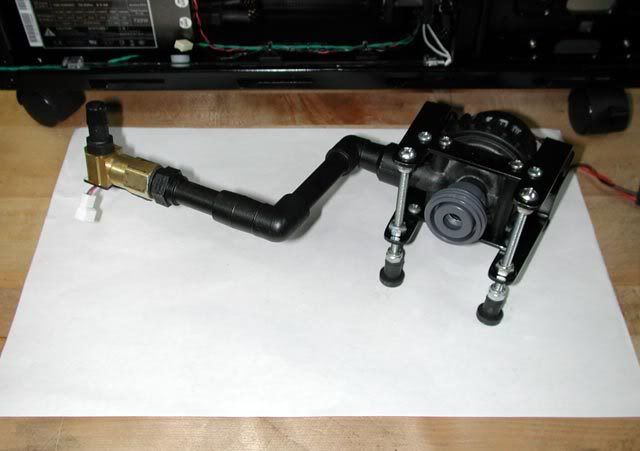
Here's how it looks all hooked up and ready to test...
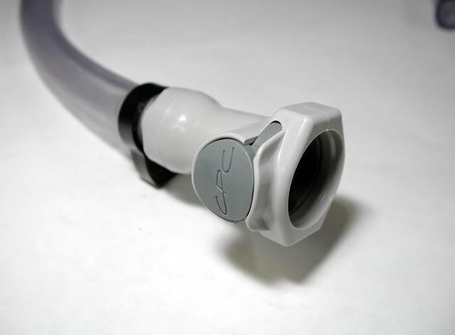
On the left, I added two auto-shut-off, quick-connect fittings with a valve in between. These guys will let me re-route the loop through a filter, transfuse the coolant, pressure test the loop, or whatever...
Here's a close-up shot of the res and plumbing...
The pump mount and plumbing just happened to fit inside the available space with 1/4" to spare. Check the gap between the pump mount and the fans... wheewww. The fit is also a function of the size of the res and the length of the brass tee fitting, so I feel very lucky it fit so well, let alone at all!
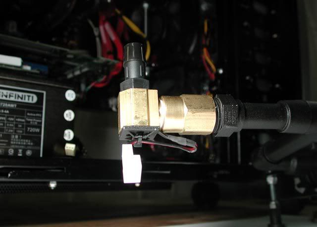
Next, it was time to test the circuit. I wanted to know if the thing was going to leak before I put water into it, so I picked up a small regulator and assembled a pneumatic water cooling circuit tester...
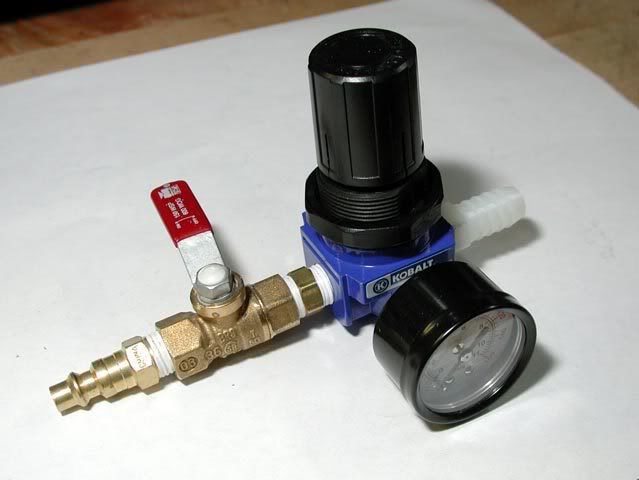
Enter this guy...
Ready to test...
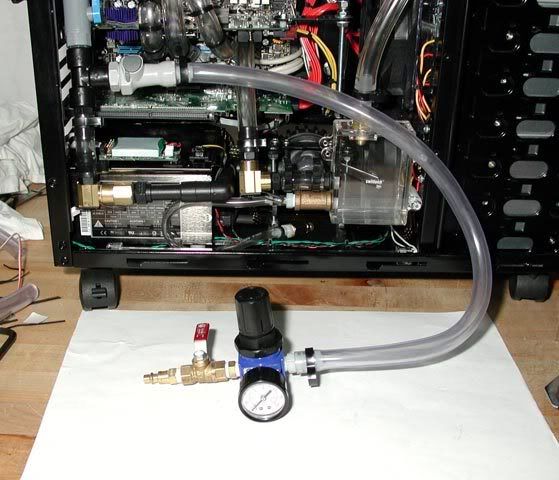
Starting off at 0 psi, I slowly brought it up to ~10psi. It's a bit uncomfortable hearing your circuit crack and pop under pressure, but after a few seconds the noises stopped and it was fine. Next, I closed the valve, disconnected the air, and heard...
Leaking air!! Bah!... I sprayed some cleaner to find the leak and there it is...
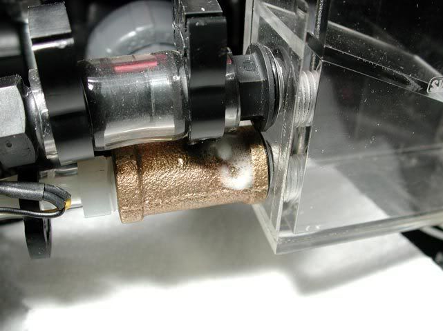
Right there through the brass fitting!. Well, it is CAST brass, which is porous and probably more prone to leaking like that because of it. Now the problem is to find a fitting that will work in the same exact spot.
I've got some more work to do...... be back soon...
(show stopper at the end)...Here's the wiring on the back all ready to be tucked in behind the side panel...
There's only .5" space to fit the cables inside the side panel...
I got it all tucked in except for one or two spots, but they'll squish in so I think the side panel should still go on just fine...
Next, it was time to assemble the front panel...
Here's the system being tested on a spare power supply. Everything is working so far...
Now, onto hooking up the water loop. First task is to assemble the pump. The plumbing was redesigned to include the temperature sensor...
Here's how it looks all hooked up and ready to test...
On the left, I added two auto-shut-off, quick-connect fittings with a valve in between. These guys will let me re-route the loop through a filter, transfuse the coolant, pressure test the loop, or whatever...
Here's a close-up shot of the res and plumbing...
The pump mount and plumbing just happened to fit inside the available space with 1/4" to spare. Check the gap between the pump mount and the fans...
wheewww. The fit is also a function of the size of the res and the length of the brass tee fitting, so I feel very lucky it fit so well, let alone at all!
Next, it was time to test the circuit. I wanted to know if the thing was going to leak before I put water into it, so I picked up a small regulator and assembled a pneumatic water cooling circuit tester...
Enter this guy...
Ready to test...
Starting off at 0 psi, I slowly brought it up to ~10psi. It's a bit uncomfortable hearing your circuit crack and pop under pressure
, but after a few seconds the noises stopped and it was fine. Next, I closed the valve, disconnected the air, and heard...Leaking air!! Bah!... I sprayed some cleaner to find the leak and there it is...
Right there through the brass fitting!. Well, it is CAST brass, which is porous and probably more prone to leaking like that because of it. Now the problem is to find a fitting that will work in the same exact spot.
I've got some more work to do...
... be back soon...nlancaster
Gawd
- Joined
- Feb 24, 2005
- Messages
- 700
Sucks about the leaky fitting. cant wait to see this thing completed.
WarMace
Gawd
- Joined
- Aug 25, 2004
- Messages
- 963
I like how you used air pressure to leak test your system. That would have come in handy for me. After the 3rd time reassembling my system I resulted to blowing one one barb and plugging the other to leak test the threads on the radiator.
Thanks guys. I fixed the leak with a new brass tee! The system held a steady 10psi for 30 minutes which I think is passing enough. The new tee is the same exact cast brass tee. I tried an extruded brass tee from Lowes that's the same dimensions, but it didn't have enough face on the end to mate with the o-ring against the res. If this new tee also leaks later on, Mcmaster has one that looks to also have the same dimensions is much better quality. And, it wouldn't be too bad to drain the system and replace it again if needed. So we'll see what happens...
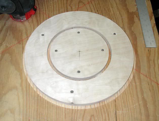
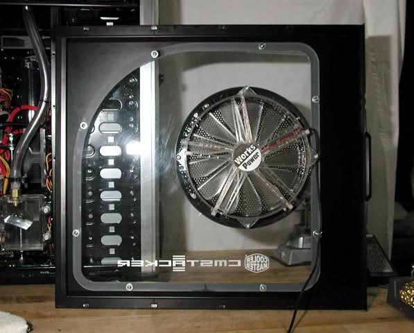
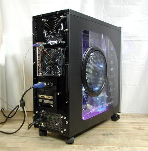
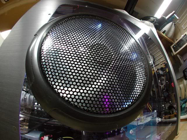
The final piece I have planned for this build is a 250mm side fan and will sit right about here...
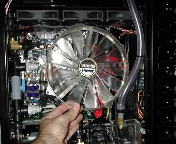
the fan by itself...
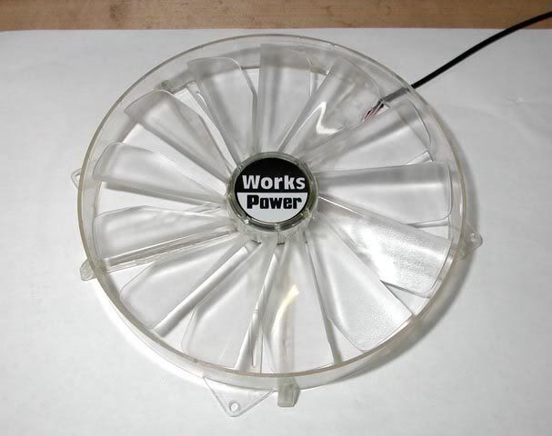
I originally planned to make a custom mold out of MDF, and then press a custom grill with modder's mesh or the like. But in the interested of time, I'm going with the original which will work just fine...
The mounting holes are at off-angles, which makes laying them out a little more tricky. I haven't decided which tool to cut it with yet. The jigsaw I've used before for cutting fan holes in plastic and it works fine, but I haven't yet tried a router and template which would leave a nice finished edge... humm...
That's all for now. For the next update, baring more show stoppers, I'll have the fan in place and the system running!
I fixed the leak with a new brass tee! The system held a steady 10psi for 30 minutes which I think is passing enough. The new tee is the same exact cast brass tee. I tried an extruded brass tee from Lowes that's the same dimensions, but it didn't have enough face on the end to mate with the o-ring against the res. If this new tee also leaks later on, Mcmaster has one that looks to also have the same dimensions is much better quality. And, it wouldn't be too bad to drain the system and replace it again if needed. So we'll see what happens...The final piece I have planned for this build is a 250mm side fan and will sit right about here...
the fan by itself...
I originally planned to make a custom mold out of MDF, and then press a custom grill with modder's mesh or the like. But in the interested of time, I'm going with the original which will work just fine...
The mounting holes are at off-angles, which makes laying them out a little more tricky. I haven't decided which tool to cut it with yet. The jigsaw I've used before for cutting fan holes in plastic and it works fine, but I haven't yet tried a router and template which would leave a nice finished edge... humm...
That's all for now. For the next update, baring more show stoppers, I'll have the fan in place and the system running!
I have the same exact fan in my Stacker 810. Since mine has the mesh circle in the side panel all I had to do was cut the aluminum fins that held the 80mm fan mount and drill two holes for the screws. The 250 finally gave me enough airflow to keep my GTX's running nice and cool.
Looked through your whole post, some really nice stuff!! Very impressive. I was thinking of getting myself a CM Stacker also... and your idea to put the rad in the top of the case is awesome... I might try a mod project like that, although it would probably only be a double or triple rad
But I gotta ask... so much awesome watercooling to see... why are you going to cover it all up with a big fan?
But I gotta ask... so much awesome watercooling to see... why are you going to cover it all up with a big fan?
pc299, it seems the original stacker side panel with the little 80mm fan bracket behind that huge circular vent was just begging for a 250mm fan. I'm glad to hear it's working so well.
Thanks! Yeah, I thought about that. I do agree it'd look better without a big fan on the side. Right now, the only fans pulling air into the case are the drive fans, and I'm afraid the air-cooled parts (ram, raid chip, mobo chips, etc.) wouldn't get enough air, especially during the hot summer months. Maybe enough air would be drawn through the vent at the bottom, across components, and out through the rad, but my thinking is a side fan would do it for sure.
But I gotta ask... so much awesome watercooling to see... why are you going to cover it all up with a big fan?
Thanks! Yeah, I thought about that. I do agree it'd look better without a big fan on the side. Right now, the only fans pulling air into the case are the drive fans, and I'm afraid the air-cooled parts (ram, raid chip, mobo chips, etc.) wouldn't get enough air, especially during the hot summer months. Maybe enough air would be drawn through the vent at the bottom, across components, and out through the rad, but my thinking is a side fan would do it for sure.
unless of course you want something bigger
Bigger? Where!
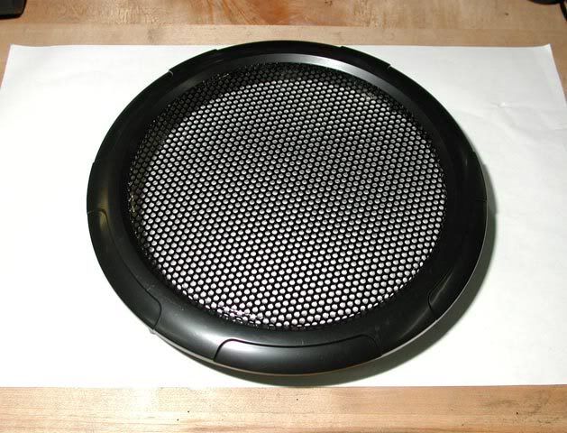
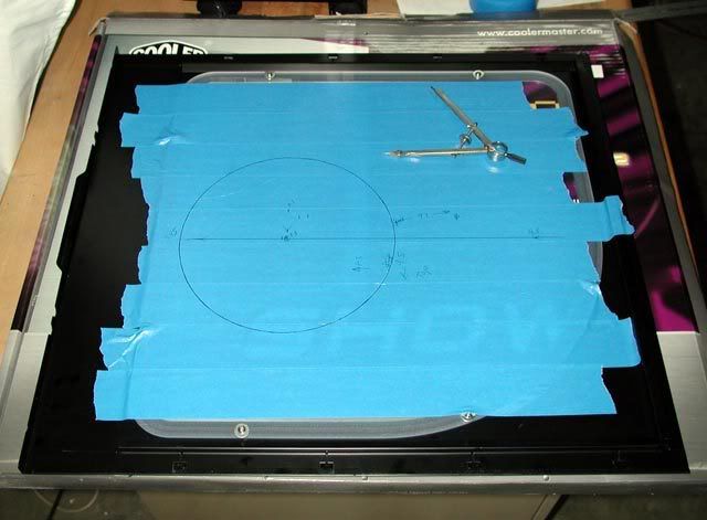
The fan is clear, which helps, but the grill is the problem (and also kind of fugly IMO with the thick bezel and dense grill). I'm going with it for now because I'm sort of out of time with this project (plus it's hot right now in N.CA). I had planned to make one that'd be less visually obstructive, but oh well . On the upside, it's a pretty big window with plenty of viewing area left over, so it'll have to do for now.I just finished cutting out the side panel for the fan and took a break. Here's how it looks up to now.
The fan bezel itself mounts to the side panel, and then the fan to the bezel. In total 8 holes need to be drilled through the panel...
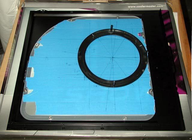
I started with the four larger holes for the fan mounting posts... By the way, I am really glad they used polycarbonate instead of acrylic, because cutting poly is a lot easier and I was afraid they used acrylic. Thank you CM for that...
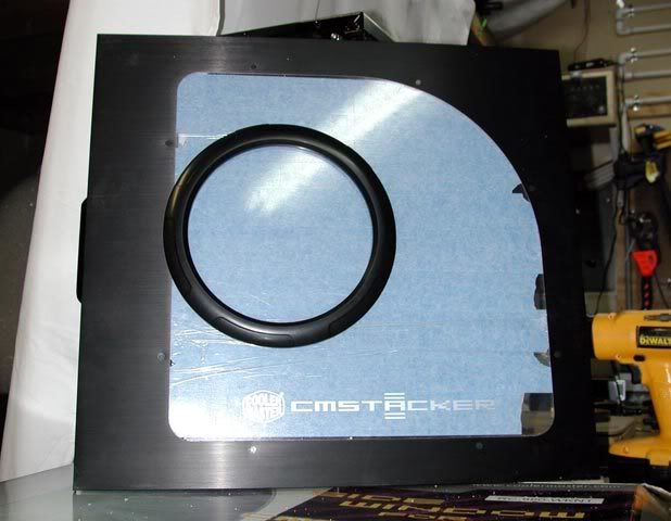
Here's how it looks from the front...
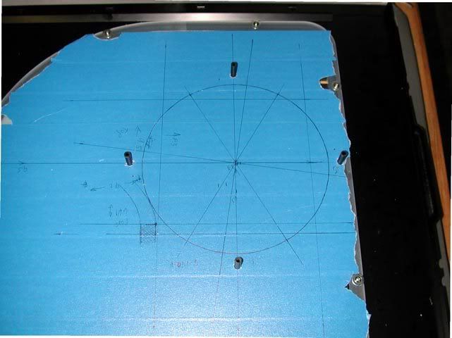
Then I did the four other holes with the bezel in place. But first I needed to find them...
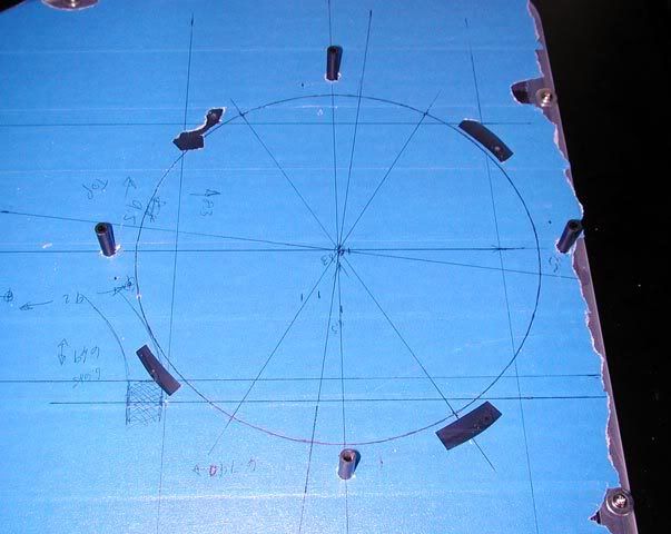
there you are...
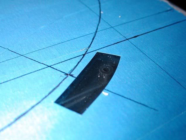
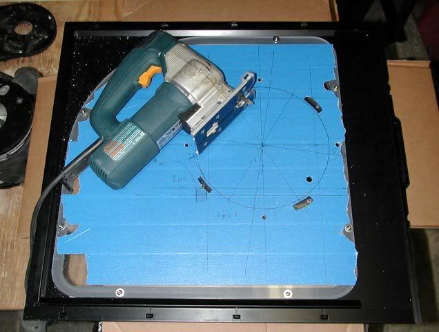
With all the holes cut and ready, it was time to cut the fan hole. On a smaller piece, I'd normally use a jigsaw and then clean up the cut either by hand with a file or on the drill press with a circular sander. Here, I wanted to go for the cleanest cut I could get, so I figured to spend a little extra time and setup a router and template to make the cut. I started with a scrap piece of 3/4" plywood and secured it to a second piece of scrap...
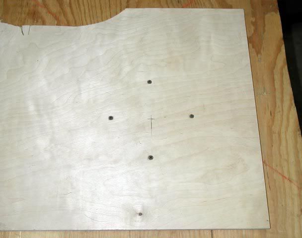
And here's the rig I setup to make the template...
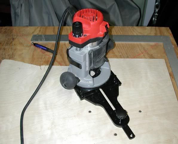
It was the first time I has used that router jig, so I started with a larger diameter first...
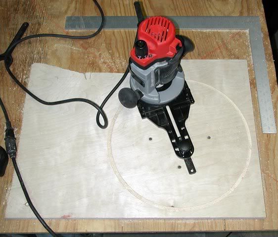
It worked great!
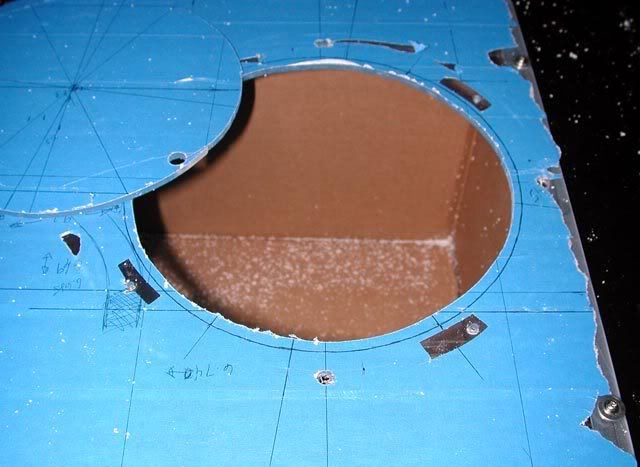
Next, I rough-cut the side panel with the jigsaw...
I had to locate that res tube to make sure the fan was going to fit. Yet another uncanny situation in this project where things just fit like it was meant to be. You may have noticed the bezel slightly extends past the window in the pic above... well, that hose clearance is the reason.
Next, I clamped the template to the panel...
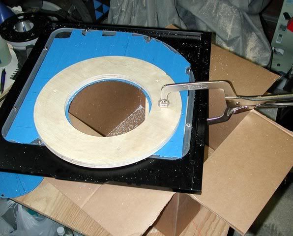
And screwed it in place from the front side...
... and this is the bit that finished it off... (crappy pic, should've blown the dust off first)
Now I've got to go clean up my garage, and then after that, it's time to put it together... back with more soon...
The fan bezel itself mounts to the side panel, and then the fan to the bezel. In total 8 holes need to be drilled through the panel...
I started with the four larger holes for the fan mounting posts... By the way, I am really glad they used polycarbonate instead of acrylic, because cutting poly is a lot easier and I was afraid they used acrylic. Thank you CM for that...
Here's how it looks from the front...
Then I did the four other holes with the bezel in place. But first I needed to find them...
there you are...
With all the holes cut and ready, it was time to cut the fan hole. On a smaller piece, I'd normally use a jigsaw and then clean up the cut either by hand with a file or on the drill press with a circular sander. Here, I wanted to go for the cleanest cut I could get, so I figured to spend a little extra time and setup a router and template to make the cut. I started with a scrap piece of 3/4" plywood and secured it to a second piece of scrap...
And here's the rig I setup to make the template...
It was the first time I has used that router jig, so I started with a larger diameter first...
It worked great!
Next, I rough-cut the side panel with the jigsaw...
I had to locate that res tube to make sure the fan was going to fit. Yet another uncanny situation in this project where things just fit like it was meant to be. You may have noticed the bezel slightly extends past the window in the pic above... well, that hose clearance is the reason.
Next, I clamped the template to the panel...
And screwed it in place from the front side...
... and this is the bit that finished it off... (crappy pic, should've blown the dust off first
)
Now I've got to go clean up my garage
, and then after that, it's time to put it together... back with more soon...I got the fan mounted up...
The router left a nice edge on the fan hole...
The back side looks like this...
... and the wire got pinned to the panel with a small improvised bracket at the bottom screw...
Fill'er up please!...
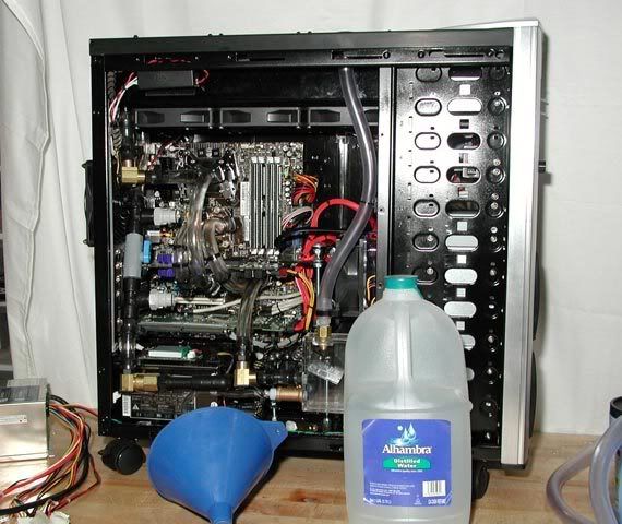
This funnel piece made it easier to keep the water going in the right place...
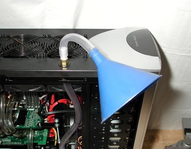
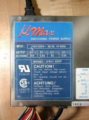
The pump was powered with this old 200W psu. The pump already uses up 1/4 of its capacity, LOL...
At first, the flow was very weak. This is my first time starting up any water cooling system, so right now I've got that sort of uneasy "what's going to happen" feeling...
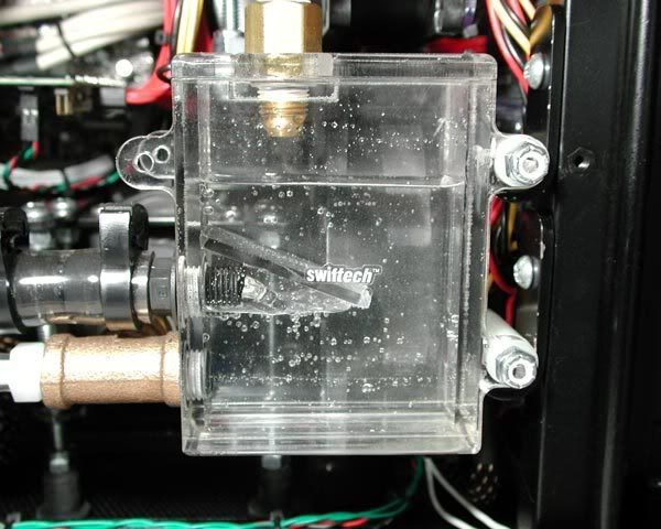
Gobs of air in the system...
The air wasn't coming out by itself and I don't know how it's normally done. I tried squeezing the lines a bunch which helped, but took forever. So I improvised. I set the regulator at 15psi and shot the system with quick, short bursts of compressed air from the top...
This seemed to do the trick. All those pockets of air where "unstuck" by the bursts of pressure and came out into the res. As long as I kept the fill tube full, the air never made it all the way down into the res. I also had to shake the top of the case quite a bit until all the air came out of the radiator. After about 10 minutes of that, all the air eventually came out and the pump went completely silent. I'm amazed at how quiet the pump is with no air in it. The flow also came on strong once the air was out of the pump.
Next, the filter was hooked up...
...and the flow re-routed by turning the valve...
The filter was new and dumped tons of air back in, so I had to start over getting the air out. Right now, it's been running for about an hour through the filter which I'm sure is plenty. Next step is to disconnect the pump, add some G11 anti-freeze and two drops of the PT_Nuke I picked a while ago from Petra's Tech Shop, and fire it up! Yeee Haa! Also, I'm extremely happy that so far not a drop has leaked (knock on wood). But I'll be watching it closely, especially that brass tee ... Enjoy...
The router left a nice edge on the fan hole...
The back side looks like this...
... and the wire got pinned to the panel with a small improvised bracket at the bottom screw...
Fill'er up please!...
This funnel piece made it easier to keep the water going in the right place...
The pump was powered with this old 200W psu. The pump already uses up 1/4 of its capacity, LOL...
At first, the flow was very weak. This is my first time starting up any water cooling system, so right now I've got that sort of uneasy "what's going to happen" feeling...
Gobs of air in the system...
The air wasn't coming out by itself and I don't know how it's normally done. I tried squeezing the lines a bunch which helped, but took forever. So I improvised. I set the regulator at 15psi and shot the system with quick, short bursts of compressed air from the top...
This seemed to do the trick. All those pockets of air where "unstuck" by the bursts of pressure and came out into the res. As long as I kept the fill tube full, the air never made it all the way down into the res. I also had to shake the top of the case quite a bit until all the air came out of the radiator. After about 10 minutes of that, all the air eventually came out and the pump went completely silent. I'm amazed at how quiet the pump is with no air in it.
The flow also came on strong once the air was out of the pump.Next, the filter was hooked up...
...and the flow re-routed by turning the valve...
The filter was new and dumped tons of air back in, so I had to start over getting the air out. Right now, it's been running for about an hour through the filter which I'm sure is plenty. Next step is to disconnect the pump, add some G11 anti-freeze and two drops of the PT_Nuke I picked a while ago from Petra's Tech Shop, and fire it up! Yeee Haa!
Also, I'm extremely happy that so far not a drop has leaked (knock on wood). But I'll be watching it closely, especially that brass tee ... Enjoy...0ptional
Don't Trust Your Friends with Your Decanter
- Joined
- Feb 22, 2003
- Messages
- 5,593
woah woah woah; hold up. This was your first water cooling system? holy crap. I wish mine was this awesome... Been through 4 now and none of them were like this...
Love to see your great work...
Indeed, I was thinking of getting one of 250mm side panel fan, and I have to hold up since most of my cutting was done by "handheld" dremel, which I don't think it'll get any satisfying result at the end.
I'll keep watching your progress...
JK
Indeed, I was thinking of getting one of 250mm side panel fan, and I have to hold up since most of my cutting was done by "handheld" dremel, which I don't think it'll get any satisfying result at the end.
I'll keep watching your progress...
JK
Love to see your great work...
Indeed, I was thinking of getting one of 250mm side panel fan, and I have to hold up since most of my cutting was done by "handheld" dremel, which I don't think it'll get any satisfying result at the end.
I'll keep watching your progress...
JK
What do you have for a case?
Forgot the model name, but it is skyhawk brand that I got several years ago.
Here is the link I posted recent cleanup work, and followings are a couple shot of side panel that I was planning to install fans.


Since I tend to keep things as simple as possible, I'd love to get one larger fan instead of 2x120mm, if I can manage this work out...
There is one more thing I want to ask since you are seemed to be a router expert.
I got a bit stucked into router... Did try with wd-40 without any success...


Do you have any suggestion / trick to get loosen this?
woah woah woah; hold up. This was your first water cooling system? holy crap. I wish mine was this awesome... Been through 4 now and none of them were like this...
Thank you! Yep, I'm a noob at water cooling. I've built plenty of air rigs, but none wc'd. Always wanted to though and, well, here it is!
I was thinking of getting one of 250mm side panel fan, and I have to hold up since most of my cutting was done by "handheld" dremel, which I don't think it'll get any satisfying result at the end.
Thanks rybeck! There's a Dremel router base accessory that I think would also leave a nice cut. It'd still need a template to ride against, but that could be cut out of plywood (or whatever) with a jigsaw and finished by hand, and then the dremel-router could be used with the template to make the cut.
Do you have any suggestion / trick to get loosen this?
Hmmm, doesn't the spindle lock work?
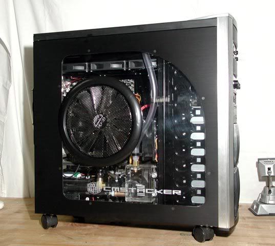
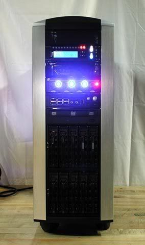
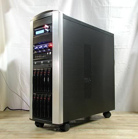
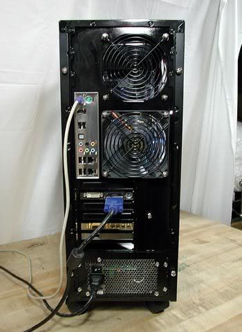
At long last the build phase of Project: Typhoon is DONE!!
I present to you the final pics of the project. Enjoy!!
Ooops, forgot to plug in the black sata cable...
I hope you enjoyed the worklog! The next steps in the project will be to install the OS, overclock, benchmark, etc. etc. which will be ongoing. I plan to post the results a little later once I get the feel of it. Thanks for watching!
Stevennoland
Limp Gawd
- Joined
- Jan 5, 2006
- Messages
- 418
Truly impressive work! Your idea for the temp sensors mounted on the brass elbows made me laugh out loud, but that is a really great idea. Also, your planning of the PCB, brilliant! Your in a class all your own. The pressure testing is also kick ass. Kudos. I hope you never have one leak. Congrats.
Emission
Supreme [H]ardness
- Joined
- Dec 6, 2005
- Messages
- 4,420
*clap* Excellent work, and excellent final shots!
Now to go work on my beast >: ).
Now to go work on my beast >: ).
Thanks Steve! Your work is out of this world, so I'm extremely flattered by your compliments, thank you! About the sensors, I wanted to keep the sensors dry (I've read they disintegrate over time) and I figured the temperature drop across the wall of the fitting has to be very nearly zero as long as it's insulated (thus the wire mount). It's not calibrated or tested, but I think it'll at least give a rough estimate of the temps, we'll see! I can only image what kind of sick sensor you'd whip up made out of solid poly with a pressed-in chunk of copper to function as a temperature pick-up. What do you think?
Emission, thank you! And also thanks for your comments along the way. Did you already start your next project? I didn't find it.
*clap* Excellent work, and excellent final shots! Now to go work on my beast >: ).
Emission, thank you! And also thanks for your comments along the way. Did you already start your next project? I didn't find it.
Nicepants42
Gawd
- Joined
- Aug 30, 2004
- Messages
- 772
That is some nice work!
From your description of filling the loop, it almost sounded like you were running the pump while filling. For future reference, it's easier to fill the loop as much as you can (rotate the case if you can) before starting the pump, that way the pump isn't running (as) dry. With a fill port like yours, it should be fairly easy to tilt the case around and get almost all the air out before you ever start the loop.
From your description of filling the loop, it almost sounded like you were running the pump while filling. For future reference, it's easier to fill the loop as much as you can (rotate the case if you can) before starting the pump, that way the pump isn't running (as) dry. With a fill port like yours, it should be fairly easy to tilt the case around and get almost all the air out before you ever start the loop.
With a fill port like yours, it should be fairly easy to tilt the case around and get almost all the air out before you ever start the loop.
With a case the size of the stacker, full with equipment and everything, it's very very heavy.
Congrats on the build, the fisheye was a little much but provided some sweet angles. Once more I'll reiterate: thank you for all the great ideas and build insight on working with the Stacker. Such a great case, I'm glad to see others using and modding them.
Until next time!
Citizen86, thank you!
Nicepants42, thanks for the tip! And also your concern about the pump running dry. Oneil is right though, this thing weighs in at 68lbs! That's why I improvised a way to purge the air out without having to flip it. Also toggled the old psu that was powering the pump on and off until there was enough water in there to run it constantly wet. After that, the air came out of the rad by shaking the case while it sat on its feet the bench. I shook it in a twisting motion and also shook it while tipped on two feet, but not too much for fear of dropping it .
Oneil, thank you! And thank you for checking out my worklog. Cheers!
Nicepants42, thanks for the tip!
And also your concern about the pump running dry. Oneil is right though, this thing weighs in at 68lbs! That's why I improvised a way to purge the air out without having to flip it. Also toggled the old psu that was powering the pump on and off until there was enough water in there to run it constantly wet. After that, the air came out of the rad by shaking the case while it sat on its feet the bench. I shook it in a twisting motion and also shook it while tipped on two feet, but not too much for fear of dropping it .Oneil, thank you!
And thank you for checking out my worklog. Cheers!nlancaster
Gawd
- Joined
- Feb 24, 2005
- Messages
- 700
Looks sweet man, I hope mine comes out looking that good.
Emission
Supreme [H]ardness
- Joined
- Dec 6, 2005
- Messages
- 4,420
JonCl: Nah I didn't start work. I'm working out parts and such, the case will be totally unique (as it isn't a "case" to begin with ).
).Nicepants42
Gawd
- Joined
- Aug 30, 2004
- Messages
- 772
Citizen86, thank you!
Nicepants42, thanks for the tip!
So what? It's not like you have to lift it completely off the floor. I'm somewhat familiar with heavy PCs.
That's my desk, with a Sony FW900 on it, speaking of heavy.
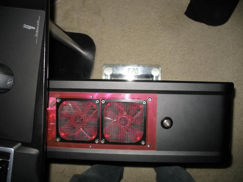
That's my rig on a scale that reads 62lbs. Sorry for the crap quality, but the scale turns off fast so I was in a hurry. I only have 4 hard drives in this PC.
I didn't have any problem tilting this thing while filling it. [j/k] How much does your air compressor weigh? [/j/k]
It was just a friendly suggestion in case you're ever stuck without a workbench or air compressor.
nlancaster, I've got a feeling it will . I look forward to your updates.
Emission, I'll watch out for it - sounds interesting!
Nicepants42, sweet looking rig you've got there. I don't think I would've guessed it was 62lbs, so I think my 68lbs isn't all that much then. Somebody should start a "how much does your case weigh" thread with the rule that all posts have to have a pic of the rig on the scale like the pic you posted! Well, anyway, where do you live? - because next time I have to purge this thing, you're invited!
btw, I've got Typhoon running nice and stable at a decent overclock I think. Coming up are some benchmark and overclock numbers...
. I look forward to your updates. Emission, I'll watch out for it - sounds interesting!
Nicepants42, sweet looking rig you've got there. I don't think I would've guessed it was 62lbs, so I think my 68lbs isn't all that much then
. Somebody should start a "how much does your case weigh" thread with the rule that all posts have to have a pic of the rig on the scale like the pic you posted! Well, anyway, where do you live? - because next time I have to purge this thing, you're invited! btw, I've got Typhoon running nice and stable at a decent overclock I think. Coming up are some benchmark and overclock numbers...
Update: Benchmarks and Overclocks
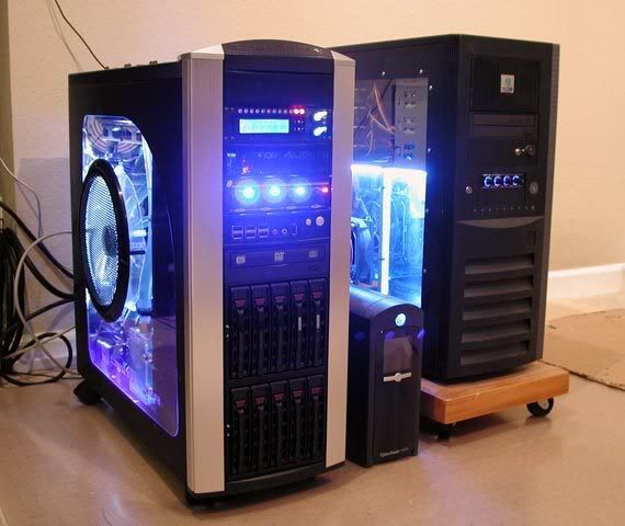
Setting up the Typhoon went very smooth. I used nLite 1.4b to slipstream the Areca RAID drivers into XP SP2 64-bit edition, which installed without a hitch. Here's a pic of Typhoon along side my other Opteron 165 rig (@2.8GHz) built with the good'old Chenbro Genie case...
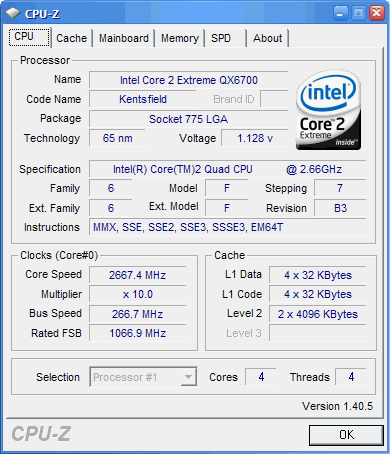
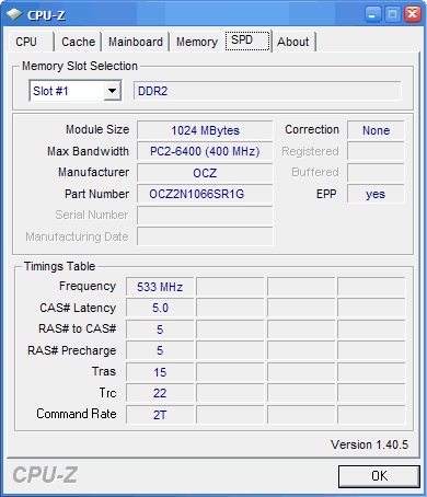
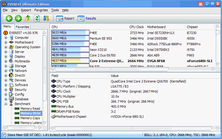
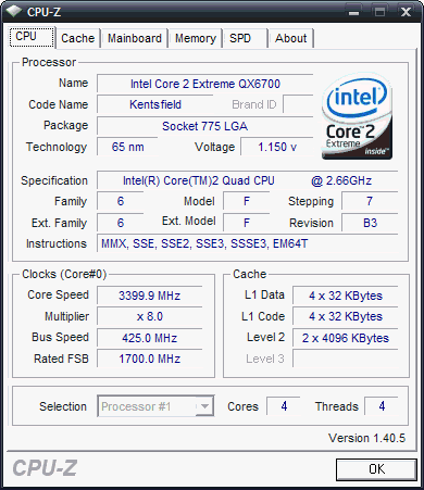
Here's how CPU-Z looked stock...
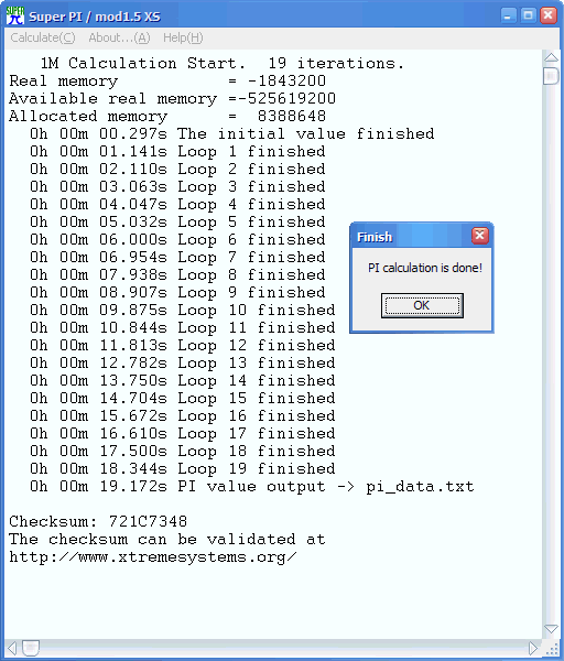
I also setup SuperPi to run all four cores simultaneously...

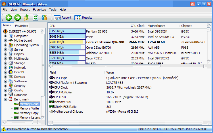
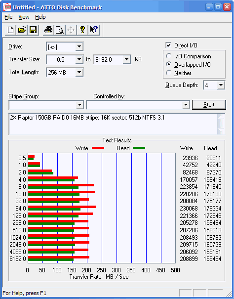
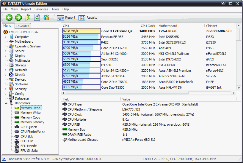
Here, the disk benchmarks are with the original 256MB cache on the Areca RAID card...

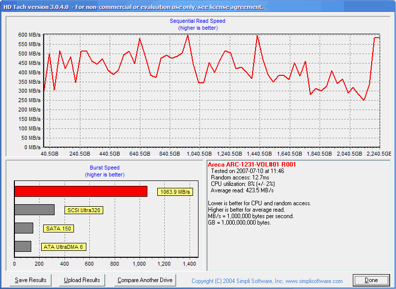
I think this score is pretty low probably due to the older Quadro FX 4400 graphics card...

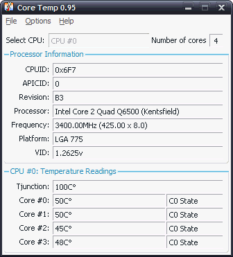
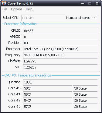
So much for stock, it's time to see what she's really got! I played around for a few hours and got it running stable at 3.4GHz (425x8). First, here's the core temps at idle...
was 7501...
was 4837...
Stock was 19.172s. My Opteron 165 rig only does ~31s! wow!...
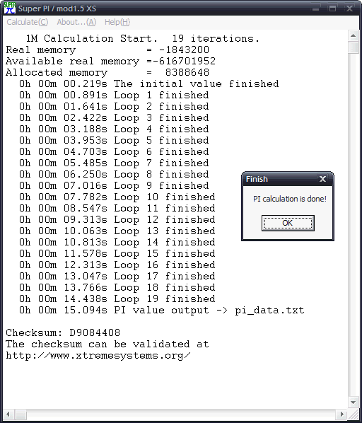
SuperPi x4 sped up by ~3s...

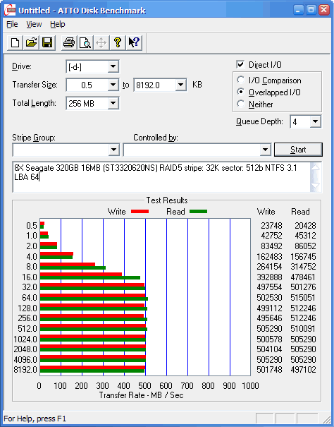
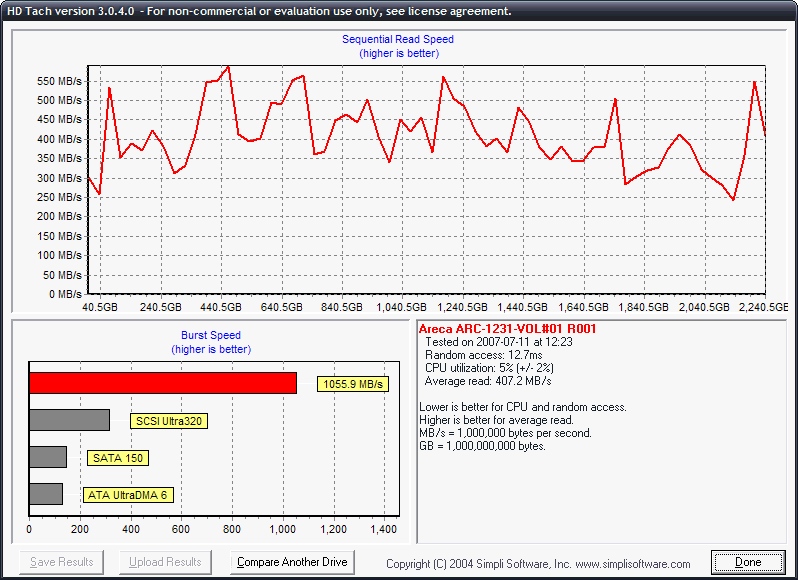
Here's where I swapped the original 256MB cache that came with the Areca card with a 2GB stick. The 2GB cache seems to make a big difference, at least in the benchmarks...
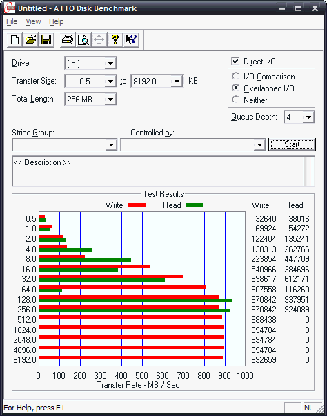
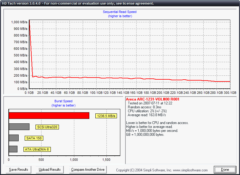
I'm guessing the extra cache is somehow causing the low Read results on later half of the benchmark - not sure...
3DMark06 came up a little. It was 2903...

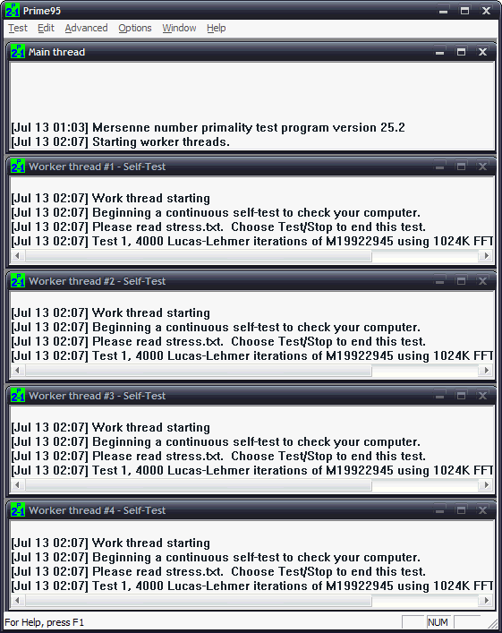
I ran Prime95 for 2 hours without a problem, but it still needs a full 8 hour stability test...
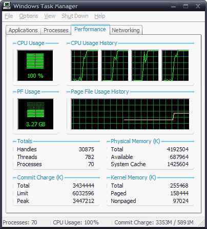
With all four cores at 100% load, the water temp just after the blocks reads ~34C, just after the rad it's ~31C, and just after the pump it's 32C. The core temps settle out between 60 and 70C (depending on the ambient temp)...
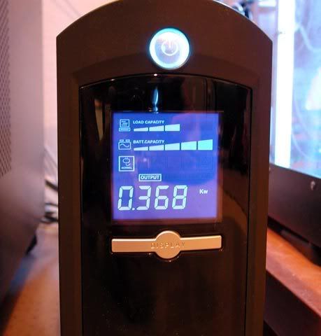
Typhoon uses ~375W, which is ~50 more than my other rig...
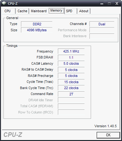
So far, the rig has been totally stable at 3.4GHz running flat out with all 4 cores loaded to 100%. I think that since the ram is DDR2 PC8500 (2X533MHz), but only running at 425, there may be some left to go. In any case, I'm extremely happy with the results. The QX6700 in Typhoon is an absolute beast compared to my Opteron 165 in the other rig, plus Typhoon is ~50% quieter!
I plan to update post #1 with summary info, but for now, I think that about raps it up for Project: Typhoon. It's been a lot of fun! Cheers!
Setting up the Typhoon went very smooth. I used nLite 1.4b to slipstream the Areca RAID drivers into XP SP2 64-bit edition, which installed without a hitch. Here's a pic of Typhoon along side my other Opteron 165 rig (@2.8GHz) built with the good'old Chenbro Genie case...
Here's how CPU-Z looked stock...
I also setup SuperPi to run all four cores simultaneously...

Here, the disk benchmarks are with the original 256MB cache on the Areca RAID card...
I think this score is pretty low probably due to the older Quadro FX 4400 graphics card...
So much for stock, it's time to see what she's really got!
I played around for a few hours and got it running stable at 3.4GHz (425x8). First, here's the core temps at idle...
was 7501...
was 4837...
Stock was 19.172s. My Opteron 165 rig only does ~31s!
wow!...
SuperPi x4 sped up by ~3s...

Here's where I swapped the original 256MB cache that came with the Areca card with a 2GB stick. The 2GB cache seems to make a big difference, at least in the benchmarks...
I'm guessing the extra cache is somehow causing the low Read results on later half of the benchmark - not sure...
3DMark06 came up a little. It was 2903...
I ran Prime95 for 2 hours without a problem, but it still needs a full 8 hour stability test...
With all four cores at 100% load, the water temp just after the blocks reads ~34C, just after the rad it's ~31C, and just after the pump it's 32C. The core temps settle out between 60 and 70C (depending on the ambient temp)...
Typhoon uses ~375W, which is ~50 more than my other rig...
So far, the rig has been totally stable at 3.4GHz running flat out with all 4 cores loaded to 100%. I think that since the ram is DDR2 PC8500 (2X533MHz), but only running at 425, there may be some left to go. In any case, I'm extremely happy with the results. The QX6700 in Typhoon is an absolute beast compared to my Opteron 165 in the other rig, plus Typhoon is ~50% quieter!
I plan to update post #1 with summary info, but for now, I think that about raps it up for Project: Typhoon. It's been a lot of fun! Cheers!
Wahoomcdaniel
Weaksauce
- Joined
- May 2, 2005
- Messages
- 117
Update: Benchmarks and Overclocks
Setting up the Typhoon went very smooth. I used nLite 1.4b to slipstream the Areca RAID drivers into XP SP2 64-bit edition, which installed without a hitch.
I googled nLite to learn what this software was for. I don't understand the part about "slippstream the Areca RAID drivers." Could you offer an explanation, please?
Nicepants42
Gawd
- Joined
- Aug 30, 2004
- Messages
- 772
Slipstreaming is where you create an installation CD with drivers or other things pre-loaded. For instance, it's fairly common practice to create a Windows XP installation CD with SP2 slipstreamed into it, so that when you reformat and re-install, you install the OS updated with SP2 instead of having to download it. In this case, it sounds like Jon just didn't want to deal with RAID driver hassles and slipstreamed them into his installation so there was no F6/etc.I googled nLite to learn what this software was for. I don't understand the part about "slippstream the Areca RAID drivers." Could you offer an explanation, please?
Wow, those are some hot cores! I don't have any experience OC'ing Quad cores, but I'd suggest getting a few second opinions on the die temps you're getting - maybe you need to re-seat the block.With all four cores at 100% load, the water temp just after the blocks reads ~34C, just after the rad it's ~31C, and just after the pump it's 32C. The core temps settle out between 60 and 70C (depending on the ambient temp)...
I live in NY, and don't get out to Cupertino much - but thanks for the offer!
If you're ever near Poughkeepsie, NY, drop a PM.Stu55, thank you very much! I'm quite happy with the way it turned out.
I used "slipstream" but I think the drivers are more like "integrated". With the drivers integrated into the install CD, there's no longer the need to press F6 at the beginning of XP setup in order to add the RAID drivers. I had my doubts that the Areca drivers where going to integrate successfully, but sure enough, they worked like a charm! I use nLite not only for RAID drivers, but also to rip unwanted/needed XP components, add others, and tweak the registry. Check Integration of nVRaid drivers into XP, W2k and W2k3 (32-bit) and Integration of nvRaid drivers into XPx64 and W2k3x64 for more details.
I'm quite happy with the way it turned out.I googled nLite to learn what this software was for. I don't understand the part about "slippstream the Areca RAID drivers." Could you offer an explanation, please?
I used "slipstream" but I think the drivers are more like "integrated". With the drivers integrated into the install CD, there's no longer the need to press F6 at the beginning of XP setup in order to add the RAID drivers. I had my doubts that the Areca drivers where going to integrate successfully, but sure enough, they worked like a charm! I use nLite not only for RAID drivers, but also to rip unwanted/needed XP components, add others, and tweak the registry. Check Integration of nVRaid drivers into XP, W2k and W2k3 (32-bit) and Integration of nvRaid drivers into XPx64 and W2k3x64 for more details.
nlancaster
Gawd
- Joined
- Feb 24, 2005
- Messages
- 700
JonCI, those core temps are very high.
On my system with, QX6700 with only a 3x120mm Koolance radiator with very quite fans and much lower flowing pumps is only hitting about 55c-60c under full load @ 3.46ghz. I have found that core temp reports are higher then nvmonitor and speedfan on my system. But you might be ok because there is a known bug in CoreTemp with Core2 processors. Intel manufactures Core2 Duos with 2 different Tjunction temps. 85c and 100c. Sometimes CoreTemp is unable to tell which Tjunction your chip has. You might want to use a few other temp monitoring programs to verify those temperatures. It seems really strange that your water would be at 34c and the procs are at 70c.
On my system with, QX6700 with only a 3x120mm Koolance radiator with very quite fans and much lower flowing pumps is only hitting about 55c-60c under full load @ 3.46ghz. I have found that core temp reports are higher then nvmonitor and speedfan on my system. But you might be ok because there is a known bug in CoreTemp with Core2 processors. Intel manufactures Core2 Duos with 2 different Tjunction temps. 85c and 100c. Sometimes CoreTemp is unable to tell which Tjunction your chip has. You might want to use a few other temp monitoring programs to verify those temperatures. It seems really strange that your water would be at 34c and the procs are at 70c.