Hell's Illusion - Project Lament II

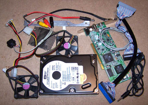
OK, onto the hardware... the motherboard, PSU, TV tuner and slim slot load DVD burner are installed and the respective cables are installed onto each device.

Illusion146m.jpg


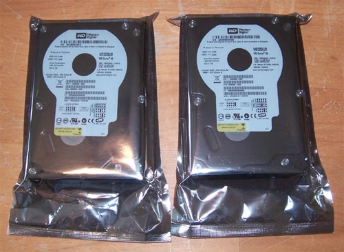
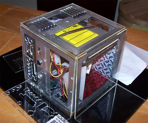
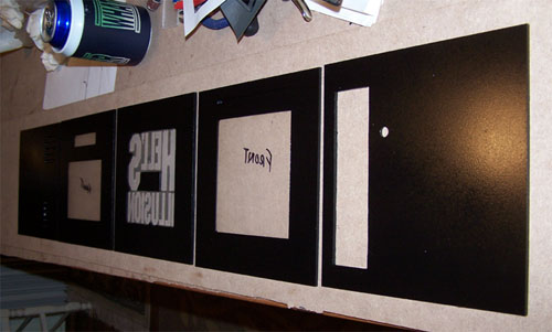
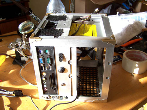
I don't want to bore you with every little detail of the hardware install so instead I will hit you with highlights and mainly show pictures. Below is the true back side of the mod, it is where everything ports out... the vacant space on the right is reserved for a WD 250GB hard drive.

Illusion147m.jpg


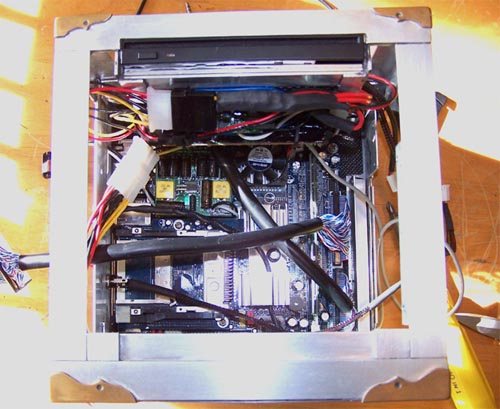
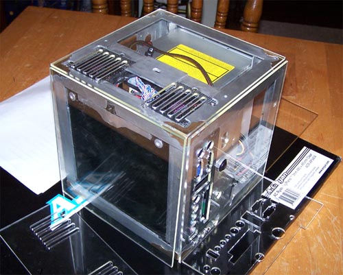
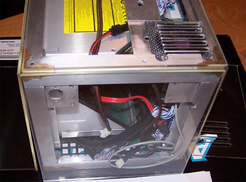
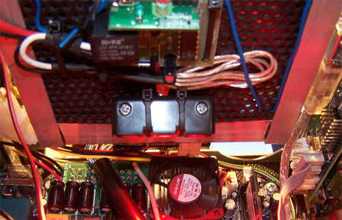
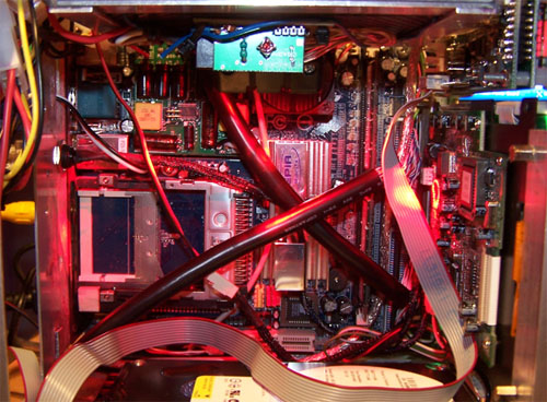
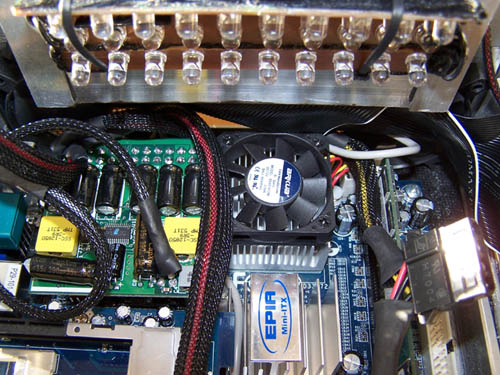
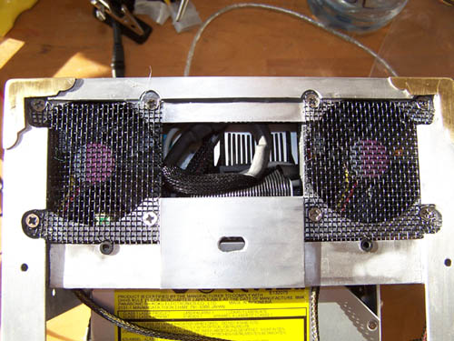
Below shows the damned processor fan, you have no idea how tight everything is just above the processor heat sink... the CD-ROM power cable, IDE cable, sound cable and the sleeved 3 LED assembly I wired up all sit over the processor. The picture below shows my "1337 Jedi oRiGaMi SkillZ", it was an hour long pain in the ass getting everything folded up and out of the way of the processor fan.

Illusion148m.jpg


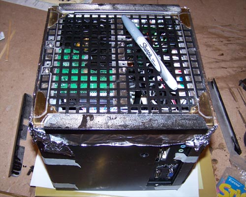
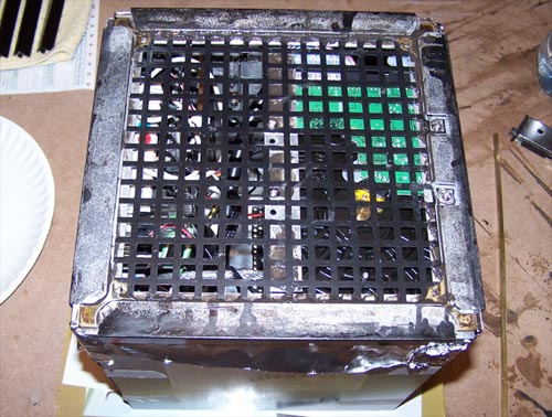
Even though you probably didn't read the above spiel about my cable ordeal, here is a shot from the top showing the cables situated tightly above the processor heat sink.

Illusion149m.jpg


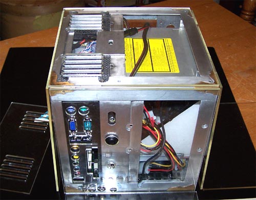
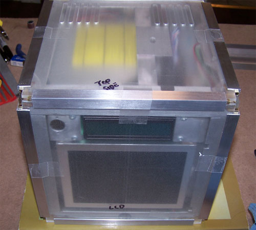
Here's a sloppy looking shot from the monitor side of the cube, I will install the LCD, Matrix Orbital and pinhole camera shortly, the IR receiver however is final installed.

Illusion150m.jpg


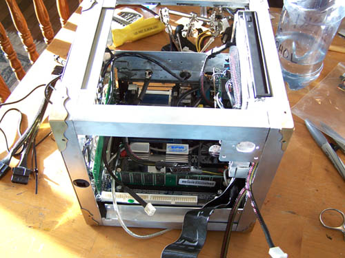
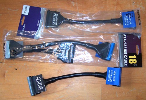
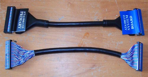
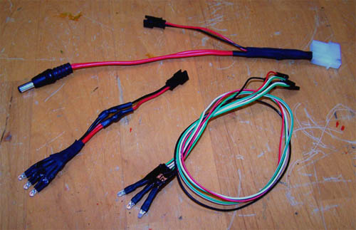
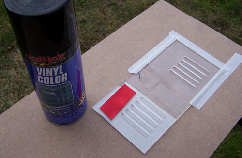
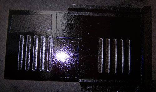
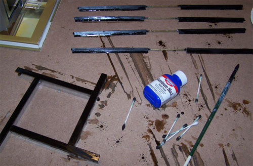
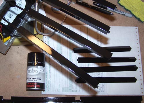
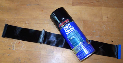
I had a black CD-ROM IDE cable that was leftover from an ASUS motherboard, it is sticking out in the picture above... I needed a black HDD cable, so with a little masking tape and some Vinyl dye I made one... and it is awesome.

Illusion153m.jpg


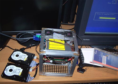
The hard drives are installed and just how tight everything sits together is now made all the more evident, I'm not small at all and it's getting harder and harder to work within the limited confines of the case.

Illusion151m.jpg


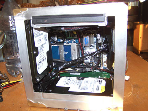
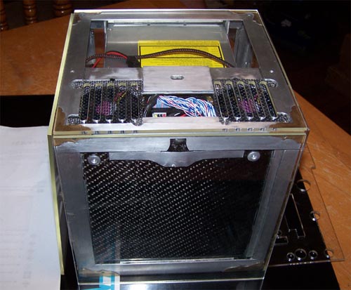
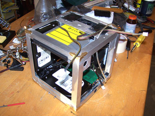
I ain't crying over making things fit, I live for a challenge. Below is a 3/4 shot showing off the freshly installed 250GB hard drives, half terabyte of storage at 8"x8"... cool.

Illusion152m.jpg


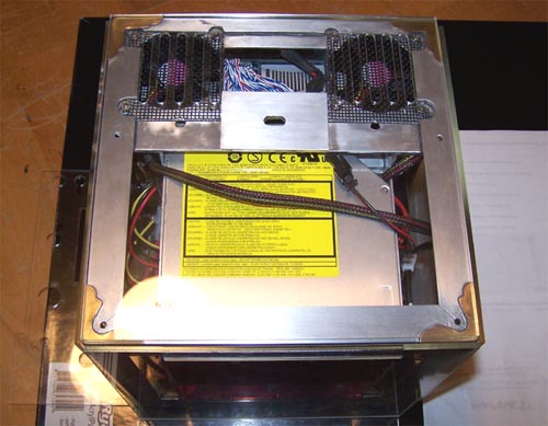
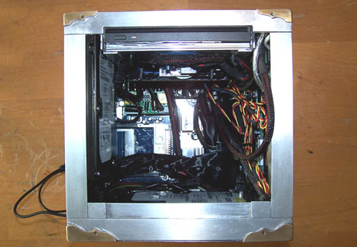
Suck it in fatty! Below shows everything installed and the nightmare of wiring that will need to be reigned in and managed, I hate wire management.

Illusion154m.jpg


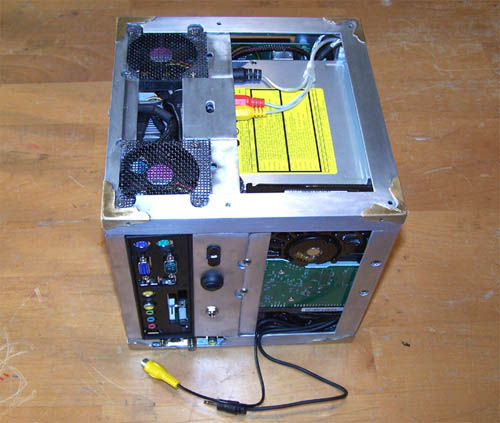
The wiring is at this point still half assed, but I wanted to throw everything in to get a feel for things. Below is the port out side of the mod, the cables at the bottom are for the 6" LCD and the IR receiver.

Illusion155m.jpg


Spinning... 3/4 view of the port side of the mod and the back of the motherboard tray...

Illusion156m.jpg


Back of the motherboard tray...

Illusion157m.jpg


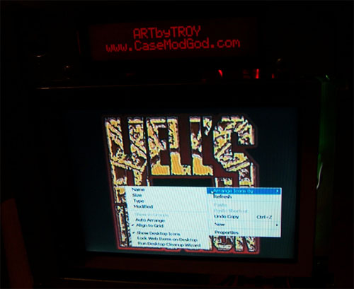
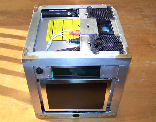
Still spinning... 6" LCD, Matrix Orbital, surveillance camera and IR receiver side...

Illusion158m.jpg


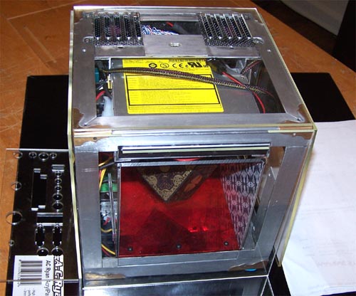
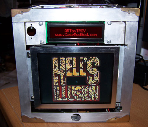
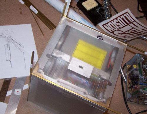
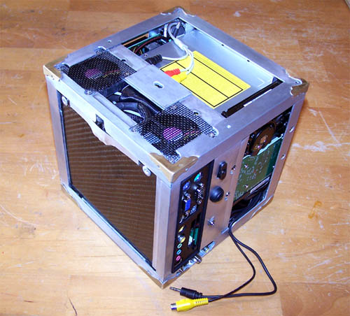
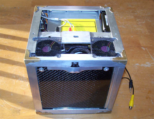
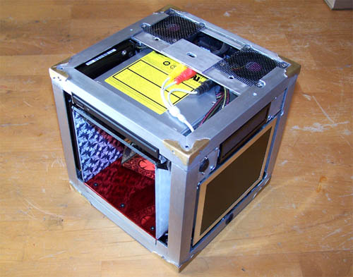
3/4 shot showing the screen side and the illusion section/DVD burner side...

Illusion159m.jpg


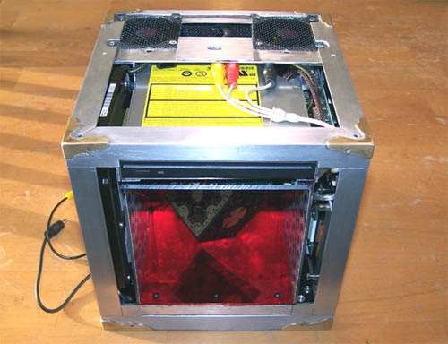
Finally a shot of the illusion section in place, I will work on the wiring a bit more tomorrow and hopefully fire it up after and install Windows MCE... WooHoo!

Illusion160m.jpg


STAY TUNED, I HAVE SUCH SIGHTS TO SHOW YOU.
 
It's entirely disassembled now, there is an issue...

The PSU I modded up is faulty, maybe I caused it by adding leads to it... maybe it was fried from the beginning, either way I should have put it on the PSU tester as soon as I got it because I am having a hard time seeing an RMA come my way for it now. Nevertheless, I just finished typing an email to the manufacturer and explained what I did, requested an RMA, sent the email to them and then promptly ordered another PW200M PSU because the magic 8-ball predicts my weak ass RMA request most assuredly will be denied.

I'm glad the PSU did not fry the mainboard, especially with the way the 2.1mm power connector from the power brick sparked when I plugged it into the PSU end, so not good. I tested the mainboard with a different PSU just to be sure that it still works and get the standard single healthy post burp... very thankful. I expect the new PSU will be here around Thursday, so until then I will work on a few other parts of it... mainly just little stuff I noticed when putting it together that could be done better.

Even though the [H] community seems for the most part disinterested in this worklog I will still either update it when the new PSU arrives or after I put it all back together.
 
I wouldn't say disineterested in the worklog per se. It's pretty damn sweet.
What I'm really looking forward to is the lore that kinda left off abruptly.

I'm still paying attention though. =>
 
oh, we're interested, just too busy looking at all the pretty pictures :) awesome work so far.

the black knight always triumphs!
 
I prefer worklogs that are very clean and without hundreds of user comments. When I first saw what you were doing, I was very disinterested, but now that I see what you have actually managed to pull off and how small it actually is, I am in awe of your talent and abilities.

Great work!
 
I really like the way this is turning out. I'm very interested. Keep up the great work...so small but so awesome.
 
Don't be fooled, I am most definitely interested. I just have a bad habit of not seeing good worklogs until they're a couple pages in.

Keep up the good work, I very much look forward to seeing this finished.
 
I think the general concensus is that the [H] community is most definately interested. We're just too busy drooling to reply :)
 
Hey all, thanks for the above... I was starting to question whether or not this mod was [H] worthy... I am also writing the next part of the fiction for those that are following along.

Back to the PSU issue... below shows the PSU plugged into the PSU tester and the red DANGER LED is glowing like mad, the -5V green LED is not lit at all and is the problem.

Illusion161m.jpg


Also, I need to mention that UPS delivery blows goats, the new power supply that should have been here today will not be here until the first of next month... here's the shipping update I got yesterday: "AN INCORRECT ROUTING AT A UPS FACILITY CAUSED THIS DELAY;THE PACKAGE WAS MISSORTED AT THE HUB. IT HAS BEEN REROUTED TO THE CORRECT DESTINATION SITE", so now the order will take eleven days by ground delivery... way to go UPS.
 
I'm sure it's a big deal to him, it's holding up his mod!

BTW: This case looks sick! I really like the attention to detail!
 
The only big deal to me is that my wife wants the dining room back, she says that it doesn't make sense to her with this mod being so much smaller than my last that the dining room could look worse than it did during the mod build last year. SWMBO especially hates it when the mod just sits there for days without me working on it... as it does now while I wait for Mondays delivery. If the PSU had made it here on time I would have been able to put it all back together and iron out any issues before Sunday (my next day off). I had planned to begin constructing the outside of the case this weekend, instead I will work a bit more on the design for the outside.
 
Z(+)DIAC said:
You are one of my heroes.

Bless You

Holy crap... thanks.

The new PW200M PSU arrived yesterday and I put it on the tester as soon as it did, but it also registers as defective... missing the -5V just like the first. I contacted tech support on 04/21 regarding questions with the first PSU, but they just thanked me for bringing "it" to their attention without providing any sort of help. I sent them an email yesterday explaining that neither of the PSU's has a -5V, according to my tester anyway (I know that the tester is functioning properly as I tested it with a known working PSU without problems) but they have yet to reply.
 
"He who opens the box, is seldom seen or heard from again."

god i love that line.

Nice project! Keep it up. . alot of hellraisers here!
 
ARTbyTROY said:
Holy crap... thanks.

The new PW200M PSU arrived yesterday and I put it on the tester as soon as it did, but it also registers as defective... missing the -5V just like the first. I contacted tech support on 04/21 regarding questions with the first PSU, but they just thanked me for bringing "it" to their attention without providing any sort of help. I sent them an email yesterday explaining that neither of the PSU's has a -5V, according to my tester anyway (I know that the tester is functioning properly as I tested it with a known working PSU without problems) but they have yet to reply.

I have the same tester, as well. I believe that with the newer ATX 2.0 power supplies, there is no -5v rail. I originally bought an Enermax 550W ATX 2.0 power supply for my rig, and I sent it back after using the power supply tester (the 'Danger' LED was lit). A different, newer, power supply did the same thing, and I didn't realize that it was because of the new ATX spec. Anyways, you should be fine with that power supply.
 
Thanks HitMan, the email I got a couple of days ago from I-Ituner networks confirms what you state, the -5V is legacy and unnecessary.

I plugged in the PSU and fired it up but it choked hard, two HDD's attached and it would not turn on... just one HDD plugged in and it turns on but it won't detect the hard drive in the bios. I have a few tests to run and also ordered a few new parts, including a 4'x4"x2.5" 320 watt PSU that likely cannot be fit into the mod... as a last ditch I will make it fit. I will try everything possible to make things work as originally intended... but if that doesn't work I will instead do whatever it takes.
 
What kind of wattage is the power brick for that PSU able to supply? Doesn't matter if the PSU can supply 200 watts if you're only using a 20 watt brick.
 
unless you sent back the other small psu, why not use one to power the board and one to power the hdd's?
 
Wow, this is the most amazing mod that I've ever seen.

I am interested in creating a similar mod as you have done with the pinhole camera.

how did you create the power cable for it?
I know that it takes 12VDC but is it as simple as wiring a 12voltDC connector to a line off of the power supply?

I have a modular PSU so ruining a cable isn't an issue, I am concerned with overloading the Pinhole camera and having to shell out another 50 bucks.

Please advise.
Thank you,
Dm
 
Detman101 said:
Wow, this is the most amazing mod that I've ever seen.

I am interested in creating a similar mod as you have done with the pinhole camera.

how did you create the power cable for it?
I know that it takes 12VDC but is it as simple as wiring a 12voltDC connector to a line off of the power supply?

I have a modular PSU so ruining a cable isn't an issue, I am concerned with overloading the Pinhole camera and having to shell out another 50 bucks.

Please advise.
Thank you,
Dm

Okay, I figured out how to wire in the Camera to the PSU molex connector.
The yellow wire is 12V, red wire is 5V and the black is ground.
Simple as soldering the wires together and mounting the camera somewhere in the case.
I think I want to go with a more inconspicuous method of mounting the camera so that it's not so obvious that its there.

My question now is how do you capture the video feed?
The camera works great going to my tv or camcorder. But cannot get it to route into my Hauppauge WinTV-401 due to differences in the DVI input of the card and the difference in the RCA->DVI cable for the camera.
The RCA->DVI cable that I have for the camera has 8 holes in the center whilst the DVI-IN on the capture card only has 4 holes.

I guess I have the wrong cable....
 
No replies...guess ARTbyTROY isn't ever coming back.

I'll never figure out how to make that damned fricking power cable now...
:mad:
 
Sorry for the late reply... I'm still here, just been taking a short break from the project (and computers in general) after my weeks vacation.

You indeed have the wrong S-video cable, I checked out your capture card hoping it had an RCA input (it doesn't) because then it would have been simple... S-vid to RCA adapters are common. I have never personally seen (or needed) a female 8 pin to male 4 pin S-video adapter but you may be able to find one online. The only other solution would be to buy a different TV tuner/capture card, I use a Leadtek TV2000XP in my main rig... it works well, has all the inputs I need and was cheap.

What is wrong with the power cable? I thought you had that part of it aced.
 
Cool project, GL with the PSU, doesn't sound fun. I'm sure you will figure something out..[H] ;)
 
ARTbyTROY said:
Sorry for the late reply... I'm still here, just been taking a short break from the project (and computers in general) after my weeks vacation.

You indeed have the wrong S-video cable, I checked out your capture card hoping it had an RCA input (it doesn't) because then it would have been simple... S-vid to RCA adapters are common. I have never personally seen (or needed) a female 8 pin to male 4 pin S-video adapter but you may be able to find one online. The only other solution would be to buy a different TV tuner/capture card, I use a Leadtek TV2000XP in my main rig... it works well, has all the inputs I need and was cheap.

What is wrong with the power cable? I thought you had that part of it aced.


Oh thank God you are back!!! :D

I got the video card part figured out.
I had the video showing on the computer by running the camera off of the 9V battery.
What I cannot figure out for the life of me is how to create the power cable.
Please see this thread to see what I've been doing wrong... :(

http://www.hardforum.com/showthread.php?t=1058816&page=2&pp=20
 
Time to crack the whip... Update 06/26/2006

The flat ribbon IDE cables I had intended using looked unsightly inside the case and covered up too much of the motherboard. There was no good way to fold them out of the way so I scrapped them in favor of the black rounded IDE cables shown below.

Illusion162m.jpg


I removed the paper tabs and the boots from the ends leaving me with the bottom cable in the picture below, the 18" dual device cable also received the same treatment.

Illusion163m.jpg


Here are the cables attached to the main board and positioned within the case, it looks much nicer without the fat black IDE cables covering up all the hardware.

Illusion165m.jpg


Next up are the two 320GB hard drives that will replace the two 250GB drives that I had originally planned on using... 640 GB, beefy!

Illusion164m.jpg


Below are the two drives hooked up to the main board and Windows Media Center being installed, it is now officially a computer. I still have some hardware to install - pinhole camera, LCD screen and Matrix Orbital - and the hard drives still need to be mounted but it is definitely working, so I am working on it again.

Illusion173m.jpg


Yesterday I went and saw my friend with the laser, we worked together all afternoon cutting the pieces of Acrylic that will make up the case exterior (Thanks again Randy - the panels truly are top notch). He also has a really cool, brand new, high end industrial printer... if I would have measured out the parts placement beforehand he could have back painted the panels too. I don't know how well it would have worked because I don't want the light to show and I am uncertain of the inks opacity, but the like he said... it could also just print out a painting template directly onto the acrylic to make masking easier, I like how he thinks and that is probably what I will do.

Illusion166m.jpg


Check out the tasty laser-y goodness... Mmmmm, crunchy. The picture below shows the laser vented top panel and the front illusion section panel with the slot for the DVD burner cut out, it's starting to come together.

Illusion167m.jpg


Below is the side panel that everything hooks into and ports out of, it came out really kick ass... especially when you factor in how it was done. The case was placed onto a flatbed scanner (connector side down) and the scanned image was then traced in Corel Draw and used as a cutting template.

Illusion168m.jpg


The following picture shows just how well everything lines up, it only took two tries cutting scrap to get it all lined up perfectly... sweet.

Illusion169m.jpg


Three-quarter overhead view of the mother board tray side, the port out side and top...

Illusion170m.jpg


Motherboard side and top... the vent slots on the top panel turned out awesome and everything fits together really nicely.

Illusion171m.jpg


Lastly, the LCD and Matrix Orbital side panel.... no real fancy laser cutting on this or the last panel other than being cut to size.

Illusion172m.jpg


STAY TUNED, I HAVE SUCH SIGHTS TO SHOW YOU.
 
Great work troy. the idea to scan the case and use corel to make the template was genius. Looking forward to seeing this one done. Keep going.
 
The acrylic panels have a few minor defects here and there, I am detail crazy (anal) and now currently working on polishing out all the tiny scratches, swirl marks and laser haze. Quality of work over quantity of work, with modding (or art) if there is anything that I can do to make it better I will likely end up doing it... so panel polishing, though tedious and in no way fun, is necessary and will make the finished mod that much better. The picture below shows the three different bottles of Novus and below them the sanding pads that came in the $14 sample kit I bought, I don't need to use the sanding pads as none of the scratches are deep (thankfully).

Illusion174m.jpg


The scratches and such are minor enough that I skipped using Novus #3 altogether, here's how it went... clean the panel with Novus #1, then polish it with Novus #2 and then clean it again with Novus #1, check your work and then repeat the entire twenty minute process. I have somewhat mixed feelings about Novus, it works and all that but then again so does toothpaste and Brasso... oh well, the sanding pads are nice.

Illusion175m.jpg


STAY TUNED, I HAVE SUCH SIGHTS TO SHOW YOU.
 
Today I worked on the wiring, I had to before I could do anything else because with everything hooked up to the little PSU... the remote control 40 LED lighting I made would not work, it does however work when connected to my test PSU. I think that I may have been splitting the power off too many times, the top cable in the picture below should fix the problem - I eliminated the power lead for the back case lighting so it now only has to power the remote lighting and pinhole camera. The old three LED array in the lower left of the picture below will not be used in the mod now (since it's power lead was eliminated) so I instead made a new three LED array that will not only light the back panel of the case but also serve a higher purpose by connecting to the mainboard as the power on, HDD activity and suspend LED's.

Illusion176m.jpg


STAY TUNED, I HAVE SUCH SIGHTS TO SHOW YOU.
 
Sweet man.... Sweet...

I know how tight everything can be when going small... I built an mITX board PC in an old DAT drive case. Boy was that tight getting the drive cables on. Keep up the excelent work.
 
I have kind of slacked on the story part of the mod, apologies for that. For those that were following it I just finished another chapter, here it is...

ACT 4

The Hell's Illusion display was sitting squarely in the center of the dining room table, if I'd been thinking I would have thrown the towel over it, "Did that guy bring it from the carnival?", Billy asked. Though I wanted to I could not lie to him, "Yes Billy, he went to get the power cord for it and then it is going right back.". He stood staring straight at the box, "Well, what is it mom?", looking down at him I couldn't help but remember that Ben had that same strange look in his eyes, "I don't rightly know what it is, but I do know that it's late little man. Give your mom a hug, it's way past time for bed.", I walked him to his room, tucked him in and closed his door. I switched off the hall and dining room lights and went into the living room to watch TV while waiting for Ben to return. The local news was on, the anchors were talking about all the destruction caused by the nights storms with sports highlights to follow and though I don't really remember it happening my long day must have caught up with me, I wound up falling asleep on the couch. I restlessly dreamt of Ben and the carnival box, of going to jail for helping him steal it and losing both the trial and my son because of it.

A loud crack of thunder, the sound of static... cold sweat and the out of place feeling that occurs when waking from a dream that feels so real. The low growling hiss and blindingly bright screen of the TV filled the room, I switched it off and sat up, how long had I slept? The VCR clock read 3:13, I could faintly hear the soft song of a music box playing. I looked over my shoulder toward the music's direction and through sleep fogged eyes noticed the moving red glow coming from the dining room, oh God... the house is on fire. I jumped up and sprint to Billy's room, in a single motion I threw open the door, switched on the light, stopped cold in my tracks and went limp as I looked down upon his empty bed. I was faint and now fighting the urge to let it all go dark, I stood up too fast and had to grab the dresser to steady myself, my heart was pounding a mile a minute and I was hyper ventilating. A cold voice was uttering 'You've lost it all, give up and die', panic attacks the doctor called them, the unfathomable severity of this one made me wish that I had health insurance and had actually filled the prescription. Breathe... slow down and breathe, over and over I told myself, but I couldn't, my hands were going numb and I couldn't think straight, my vision was reduced to peripheral flashes of light and my ears were ringing off the hook. The rational voice inside me kept repeating slow down and breathe, but there was that other voice inside louder than my own repeating 'You've lost it all, give up and die!', somehow above the ringing and everything else I could faintly hear Billy's voice calling, "Mom, come here! You've got to see this!".

I heard him, it was definitely Billy, my heart was in my throat and I still felt half paralyzed as I worked my way into the hallway toward the sound of his voice. My head all hazy and spinning I bounced a bit off the hallway walls before finally catching breath proper and getting my legs back under me. "Mom, come here!", he called out again as I stumbled toward the dining room, my breathing was finally starting to level out when I rounded the corner flipping on the dining room light. Billy stood staring at me with his mouth open, he appeared shaken by the sight of me and finally asked in a near whisper, "Are you okay mom?". I tore my gaze from him long enough to see my reflection in the mirror, I looked shades of pale with dark circles under my eyes and beads of sweat on my forehead, "I'm okay", then another deep breath, "I'm okay, now.". He ran over to me and I grabbed him, after holding him tightly and rocking back and forth I finally calmed myself enough to ask him what he was doing. Looking squarely into my eyes he exclaimed, "I used the power cord from my video game and it fit right in, I have been playing for a couple hours now and it says I only have two moves left.". I looked up from him to the illusion box on the table, it was glowing and the seemingly simple display box was now entirely ablaze with light and motion. "It's a game mom, and I'm winning."
 
I spent some time working on the graphic for the carbon fiber side panel, I plan to make about three different designs and have the best one cut out of cherry chrome vinyl for application to the panel, here is design #1. The inner lettering that is white will be masked off from the inside of the panel and will not be vinyl dyed, when combined with the LED back lighting and carbon fiber it should look pretty cool.

Illusion00mv.jpg
 
After thinking over the past couple months about this mod I decided there was a need to simple things up and there are a few reasons why. I planned the internal part of this mod really well, but had no plan for attaching the outer acrylic panels... the method I have come up with does not allow for the side mounted hard drive since it attaches directly to the corner angle. The hard drive that was removed would have had questionable ventilation to it's underside anyway, with a single drive mounted to the openly vented case bottom the top fans become unnecessary... color them gone. I wanted to lighten the load to the power supply so that the 6" LCD could lose the external 12V power adapter and run PSU direct, so the HDD, both fans, the pinhole camera (a novelty that would have been lost in a sea of novelty) and the TV tuner card + IR receiver (piece of crunk) have all been removed.

Illusion177m.jpg


With all the above parts removed I once again fired up the little computer, plugged in the 6" LCD monitor and set it up in the BIOS. Next, I installed Windows and all the drivers and the small LCD worked perfectly through it all powered by the tiny PSU... right as I was about to give myself a pat on the back I remembered that I had not tested the remote control lighting. I grabbed the remote and pressed the on switch... the PC powered off... not good. I tried it a couple more times before deciding that 40 LED's might have been a bit overkill to begin with, two Lazer LED's are not as bright or impressive as the LED array I built, but is more realistic.

Illusion180m.jpg


In the top right of the above picture is the homebrewed LED lighting that was removed from the remote sensor and the bottom left shows the Lazer LED's that will replace it. I screwed together and notched the edges of the Lazer LED's so that the zip ties don't move around and two rubber grommets were used to spread them apart to space out the lighting. Below shows everything ready for soldering with the heat shrink ready after.

Illusion181m.jpg


I plugged everything back in to test fire the lighting, the following picture shows the zip tie mounting method for the LED's and remote sensor...

Illusion183m.jpg


And below is the case interior lit up by the Lazer LED's, not nearly as bright as the 40 high intensity LED's I had intended to use, but still bright enough to light things up.

Illusion184m.jpg


It's alive, working properly and looking very sweet... next up, the money shot. I still have a few things left to do before I begin working on the outer panels, I may in fact wind up entirely re-doing the outer panels.

Illusion185m.jpg


The 6" LCD monitor is a bit clearer in real life than it looks in the following picture, but it does show the tiny monitor with open windows on it doing stuff and/or things. Pretty sweet so far, but I still have not come up with a finalized attachment method for the outer panels... that will be next.

Illusion186m.jpg
 
I spent a few hours with the polishing cloth and Novus to get the worst of the scratches out of the Acryl Panel. Clear contact paper applied to both sides should keep the panels from getting any more damage while I use them in mocking up assembly of the external casing for the mod.

Illusion187m.jpg


It took me forever and a day to come up with a plan for building the outside casing for this mod. I had at first wanted the side panels to be hinged at the bottom so that they could fold down when the top was removed, which would've ultimately proven problematic so I nixed the idea. Next I thought about making two sides on hinges and two sides where the panels would slide up and out when the top was removed, I killed that idea too. My grandmother used to say "keep it simple stupid", it has proven to be true for this mod so far and with that in mind I came up with how I'm going to do it.

Illusion188m.jpg


Hollow square brass rods and 1/2 inch corner alum angle, I've probably already said this somewhere earlier in the log but I love alum angle, it makes making stuff easier. I plan to connect everything together so that the entire outer casing can be removed in one solid piece, this will require moving the power button to the case bottom, but that isn't a big deal. You can also see the final design sketch in the picture below that showing how I intend to pull it all together, it is kind of vague but should make sense soon enough.

Illusion189m.jpg


I cut the 1/4" corner alum angle into 7" lengths and the brass rods into 3" lengths, I also cut four pieces of 1/2"x3/4" corner alum angle to 7" that will be attached to the bottom of the mod.

Illusion190m.jpg


I scuffed up all the inside edges and JB-welded the square brass rod sections into the ends of the alum, eight were made to cover the edges, I also polished up the outside of the alum angle... I probably won't leave it as is but will wait and see.

Illusion191m.jpg


Below is a mock up to determine mask positioning for the panel back painting...

Illusion192m.jpg
 
Next is a close up of the bare corner, I am still not ready to spill the beans on what I intend to do yet so you will have to wait... it will all make sense soon enough.

Illusion193m.jpg


Since I don't want to screw anything up I decided to do a test run with the vinyl dye, below shows the scrap test piece.

Illusion194m.jpg


Next shows the backside still wet after four coats of vinyl dye...

Illusion195m.jpg


And here is what it looks like post test, it looks entirely good to go... so the next step is to prep all the panels for paint.

Illusion196m.jpg


The weather here in Michigan has been unseasonable for this time of year, the temperature is almost 50 degrees in mid December... unbelievable. Since the good weather will not last I decided to take full advantage of it and work to finish this bitch and quick, doing so required finding a local vinyl cutting company to create a cleaner back panel decal than the one I made, the hand cut decal was too big anyway so I'm not crying about it. Jason at FX Graphics did me a solid and cut a couple new back panel decals on the spot, the best part of the deal is I now know a kick ass vinyl guy that lives only ten minutes away. In the picture below you can see my incorrect hand cut job on the left and the two perfect machine cut decals on the right, this being done I am almost ready to begin vinyl dying the external panels.

Illusion197m.jpg


I began prepping the panels for back painting beginning with the 'Hell's Illusion' decal side, wasting no time I installed it and then cut the back side out for the lettering. I also cut out the illusion section and the LCD and Matrix Orbital spots out on their respective panels so they are now ready for paint.

Illusion198m.jpg
 
I had to re-cut the side that everything ports out of, the nice laser cut panel I had intended to use would not work with the new design for the outside casing, below shows the simplified design... not quite laser cut, but close.

Illusion199m.jpg


The following picture shows all the panels lined up awaiting a couple coats of vinyl dye, it's starting to get dark so I have to work quick.

Illusion200m.jpg


Using a hair dryer in between spraying I managed to get four coats down before it went pitch black outside, below you can see the panels after I removed their contact paper masks.

Illusion201m.jpg


The final bit for today involved mocking the entire thing up again to make sure everything lines up... which it so far appears to, below shows where I'm at.

Illusion202m.jpg


Ok, I wasted a bunch of time trying first to chemically blacken the aluminum edges...

Illusion205m.jpg


And then trying to prepaint them...

Illusion206m.jpg


The side panels were all taped in place then the bottom edge pieces were lined up and traced with a silver Sharpie to make their placement easier.

Illusion208m.jpg


Below shows the four bottom edge pieces installed.

Illusion209m.jpg
 
Back
Top