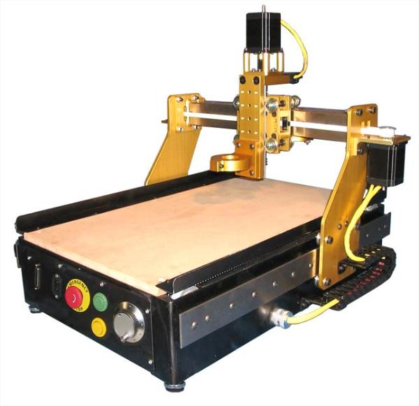
I had a little time over the weekend, so I thought I'd make something special for everyone that has been following this project. This is a video walkthrough of OSIDIAS. It explains how some of the components fit together, and I cover some of the design basics. Although I've left out a few details, I think you'll understand the project a little better. Enjoy!
http://www.vimeo.com/8832516
http://www.vimeo.com/8832516